12F343 - 3Ø 7' Double Deadend Alley Arm
Revision 4
Aug 31, 2020
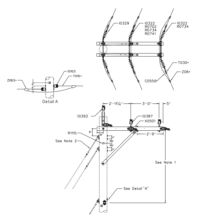
Notes:
- Minimum 7’-0” for poles up to 45’ in height. Increase spacing to 8’-0” for poles 50’ and taller.
- Engineer must specify the size & number of down guys depending on conductor design tension, line angle, available down guy lead, soil class and span length. Refer to T&D Guideline Section 4-6 and Compatible Unit Sections A and G. Down guy(s) or self-supporting poles are required for 795 kcmil AAC alley arm framing.
- Refer to T&D Guideline 4-23-1.0 for allowable construction angles.
| Compatible Unit | Description | Quantity |
|---|---|---|
| C0550 | Tap Wire, Insul 4/0 Soft Drawn Copper | 40 |
| I0103 | Insulator, #2 Single Point Secondary Rack | 2 |
| I0388 | Insulator, Sgl Polymer Vise-Top Insulator - 5/8" x 8" Pin Fiberglass Crossarm Mount | 4 |
| I0393 | Insulator, Dbl Stl Pole Top Pin w/ Polymer Vise-Top Insulator (For Pole Top Deadending Only) | 1 |
| I0322 | Insulator, Sgl DE Insulator w/ 5/8” Eye Nut - One-Way DE | 4 |
| I0329 | Insulator, Dbl DE Assembly w/ 20” D.A. Bolt - Two-Way Pole Mount DE | 1 |
| R0702 | Bolt, Double Arming 5/8" x 20" | 1 |
| R0734 | Washer, Double Coil Spring 5/8" | 2 |
| R0741 | Washer, Square Flat 2" Sq with 11/16" Hole, Galv Steel | 4 |
| R1115 | Split-Bolt, Pole Top | 1 |
| T010+ | Deadend, Preform | 2 |
| T030* | Clamp, Straight Line Deadend | 6 |
| X0551 | Crossarm, 7' Fiberglass Alley Arm | 1 |
| Z06* | Connector, Wedge | 6 |
| Z06+ | Connector, Wedge | 2 |