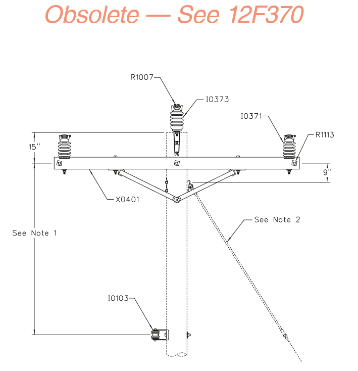
12F360 Obsolete - 3Ø 795 AAC Single Tangent Arm
Revision 4
Apr 17, 2012
Notes:
- Minimum 7’-0” for poles up to 45’ in height. Increase spacing to 8’-0” for poles 50’ and taller.
- Engineer must specify the size & number of down guys and anchors depending on conductor design tension, line angle, available down guy lead and span length. Refer to T&D Guideline 4-6 and Compatible Unit Sections A and G.
- Crossarms to be set to split the angle in the line. Guy should be set in the plane of the crossarm if possible.
- This assembly is intended for 795 kcmil AAC (Arbutus) primary conductor installed with a maximum working tension of no more than 4,000 lb/Ø. For framing conductors with a maximum working tension of 2,500 lb/Ø or less refer to Assembly Unit 12F303.
| Compatible Unit | Description | Quantity |
|---|---|---|
| I0103 | Insulator, Single Point Secondary Rack | 1 |
| I0371 | Insulator, Sgl Vertical Post Insulator - 3-3/4" x 4-3/4" Wood Crossarm Mount | 2 |
| I0373 | Insulator, Sgl Vertical Post Insulator - Pole Top Mount | 1 |
| R1007 | Clamp, Line Post Insulator 795 - 1272 AAC/ACSR - w/ o Armor 0° - 45° Line Angle | 3 |
| R1113 | Split-Bolt Assembly, 5/8" x 6" Machine Bolts | 1 |
| X0401 | Crossarm 10' Single 4-Steel Pin Crossarm | 1 |