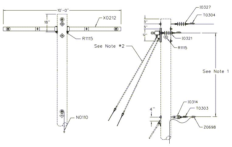
12F365 - 3Ø 795 AAC Flat Deadend
Revision 5
Jul 29, 2009
Notes:
- Minimum 7’-0” for poles up to 45’ in height. Increase spacing to 8’-0” for poles 50’ and taller.
- Engineer must specify the size & number of down guys and anchors depending on conductor design tension, line angle, available down guy lead and span length. Refer to
- Crossarms to be set to split the angle in the line. Guy should be set in the plane of the crossarm if possible.
- This assembly is intended for 795 kcmil AAC (Arbutus) primary conductor installed with a maximum working tension of no more than 4,000 lb/Ø. For framing conductors with a maximum working tension of 2,500 lb/Ø or less refer to Assembly Unit 12F310.
| Compatible Unit | Description | Quantity |
|---|---|---|
| I0314 | Insulator, Sgl Insulator w/ 14" Eye Bolt - One-Way Pole Mount DE | 1 |
| I0321 | Insulator, Sgl DE Insulator (Fittings: Clevis-Eye) | 2 |
| I0327 | Insulator, Sgl DE Insulator w/ 14” Eye Bolt - One-Way Pole Mount DE | 1 |
| N0110 | Ground Plate Installation on Wood Pole | 1 |
| R1115 | Split-Bolt, Pole Top | 1 |
| T0303 | Clamp, Straight Line 336.4 kcmil (3/0 - 477 kcmil ACSR, 4/0 - 556 kcmil AAC) | 1 |
| T0304 | Clamp, Straight Line 795 kcmil (336.4 - 1113 kcmil ACSR, 336.4 - 1200 kcmil AAC) | 3 |
| X0212 | Crossarm, 10' Deadend 4-Pos. Hvy. Duty | 1 |
| Z0608 | Connector, H Type Al Compression 336.4 AAC to #6 Sol - #2 Sol | 1 |