12F616 - Switched Capacitor Bank VAR Controlled
Revision 10
Nov 16, 2021
Notes:
- Engineer must specify Compatible Unit for desired capacitors:
DB0115 - 300 kVAR (3 - 100)
DB0116 - 450 kVAR (3 - 150)
DB0117 - 600 kVAR (6 - 100)
DB0118 - 900 kVAR (6 - 150)
DB0119 - 1350 kVAR (9 - 150)
If a capacitor bank size different than those listed above is required, the bank must be custom assembled from individual capacitor tanks. - The capacitor bank, switches, surge arresters, junction box, control cabinet, and current sensor must be grounded. Refer to the grounding diagram for Compatible Unit N0272.
- Relocate neutral if necessary to provide clearance between bottom of capacitor tank and neutral.
- A current will flow between the capacitor rack and ground when capacitor switches are open. If a break should occur in the ground wire, a hazardous condition would exist upon opening the switches. The ground wire must be visually checked when climbing the pole.
- No work will be done on pole at or above capacitor bank level until the capacitors have been disconnected from line and discharged as follows:
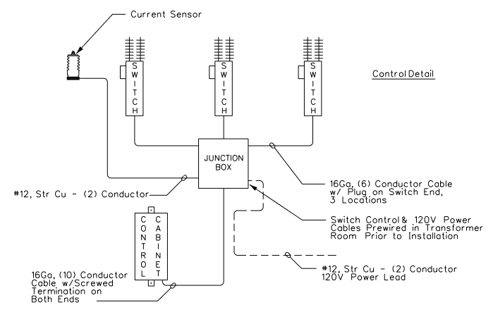
Before touching capacitor terminals, disconnect capacitor bank from the supply source, allowing five minutes minimum for discharge, then short and ground all terminals. - Refer to District Drawing B-1054, latest revision, for control wire schematic.
| Compatible Unit | Description | Quantity |
|---|---|---|
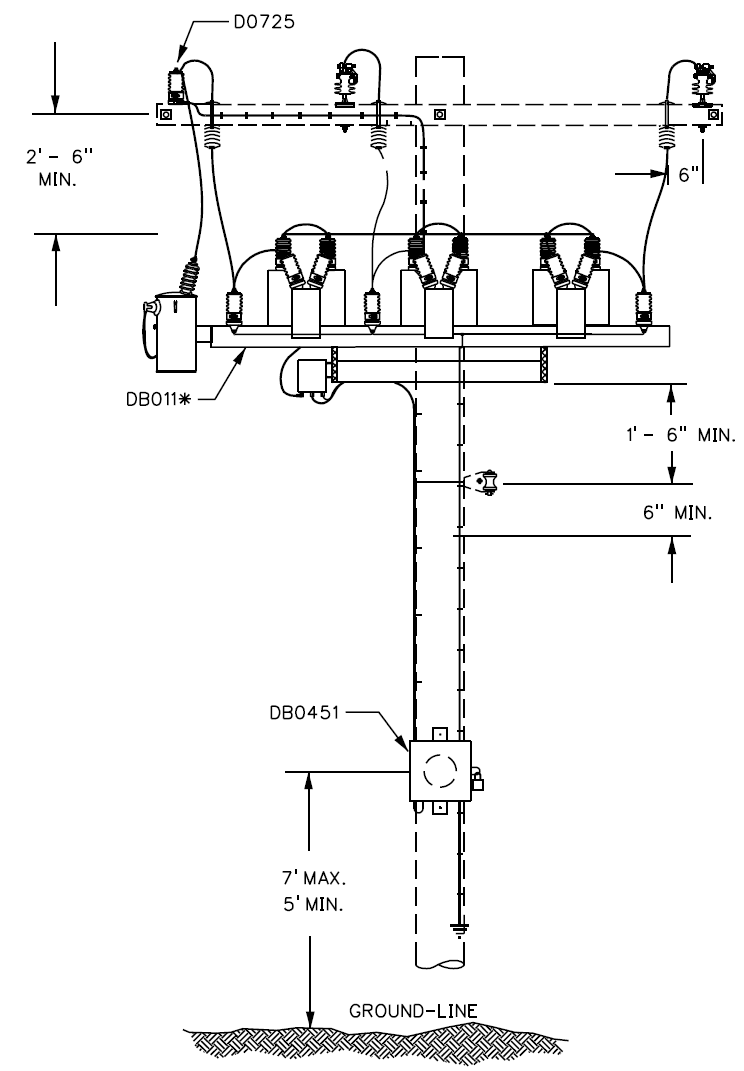
| DB011- | Capacitor, 7.2/12.47kV 3Ø Switched Bank | 1 |
| DB0451 | Controller, Switched Capacitor, Automatic | 1 |
| D0725 | Current Sensor, 15kV Line Post | 1 |
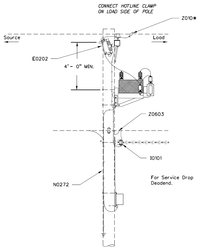
| E0202 | Cutout, 100A 15 kV Polymer | 3 |
| I0101 | Insulator, Spool w/ Rack #1 | 1 |
| N0272 | Switched Capacitor Bank Ground | |
| R0102 | Bracket, Cutout Xarm Mount w/ 2, 3/8" x 6" CB | 3 |
| Z010* | Clamp, Hotline Al | 3 |
| Z0603 | Connector, Squeezon Al (#3) 2/0 - 3/0 to #6 - #1 | 2 |