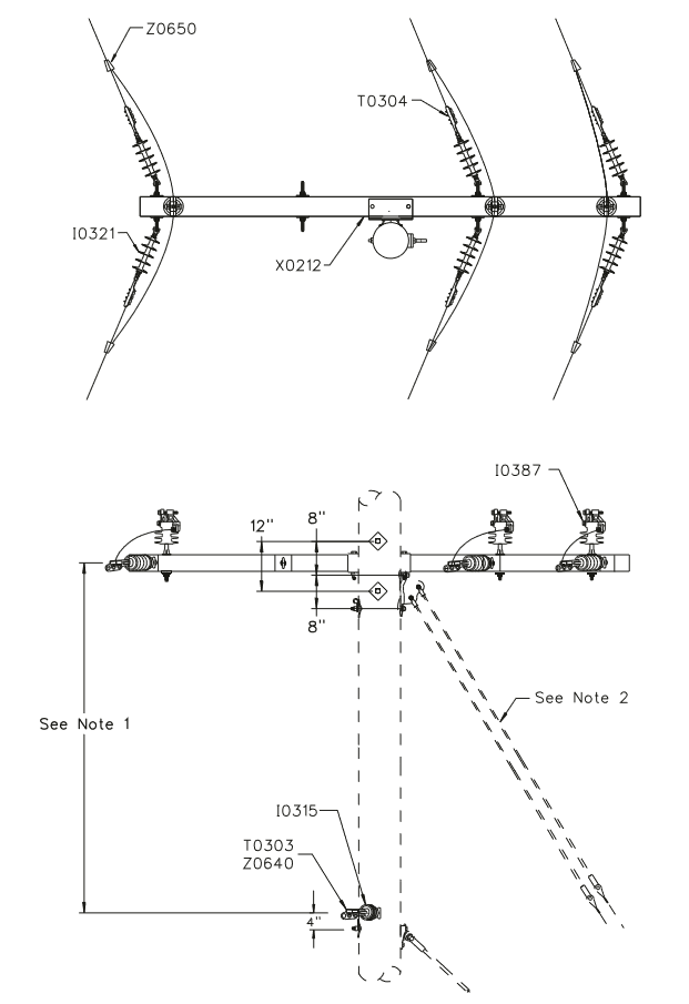
12F376 - 3Ø 795 AAC Flat Double Deadend Underbuild
Revision 3
May 9, 2012
Notes:
- Preferred spacing between crossarm and neutral is 8'-0". Minimum allowable spacing is 7'-0".
- Engineer must specify the size & number of down guys and anchors depending on conductor design tension, line angle, available down guy lead and span length. Refer to
- Crossarms to be set to split the angle in the line. Guy should be set in the plane of the crossarm if possible.
- This assembly is intended for 795 kcmil AAC (Arbutus) primary conductor installed with a maximum working tension of no more than 4,000 lb/Ø. For framing conductors with a maximum working tension of 2,500 lb/Ø or less refer to Assembly Unit 12F312.
| Compatible Unit | Description | Quantity |
|---|---|---|
| I0315 | Insulator, Dbl DE Assembly w/ 20” D.A. Bolt - Two-Way Pole Mount DE | 1 |
| I0321 | Insulator, Sgl DE Insulator (Fittings: Clevis-Eye) | 6 |
| I0387 | Insulator, Sgl Polymer Vise-Top Insulator - 5/8" x 6-1/2" Pin Fiberglass Crossarm Mount | 3 |
| T0303 | Clamp, Straight Line 336.4 kcmil (3/0 - 477 kcmil ACSR, 4/0 - 556 kcmil AAC) | 2 |
| T0304 | Clamp, Straight Line 795 kcmil (336.4 - 1113 kcmil ACSR, 336.4 - 1200 kcmil AAC) | 6 |
| X0212 | Crossarm, 10' Deadend 4-Pos. Hvy. Duty | 1 |
| Z0640 | Connector, Wedge 336.4 AAC/ACSR to 336.4 AAC/ACSR | 2 |
| Z0650 | Connector, Wedge 795 AAC/ACSR to 795 AAC/ACSR | 6 |