12F325 - Double Circuit Flat Line Angle
Revision 9
Jun 15, 2022

Notes:
- Minimum 8’-0”. Only to be installed on poles 50’ and taller.
- Engineer must specify the size & number of down guys and anchors depending on conductor design te`nsion, line angle, available down guy lead and span length. Refer to
- Crossarms to be set to split the angle in the line. Guy should be set in the plane of the crossarm if possible.
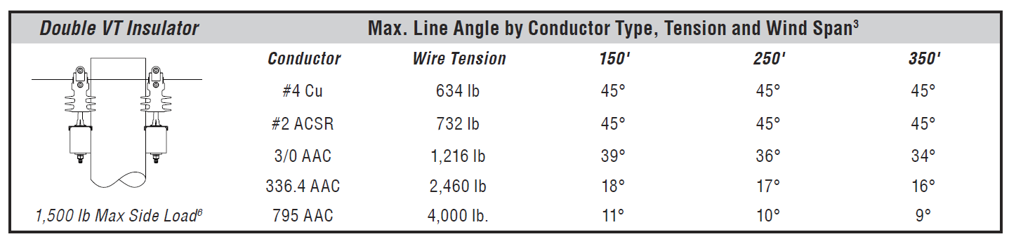
- To avoid conductor contact during fault conditions, install conductor spacers (Compatible Unit I0320A-B) on span lengths greater than 150 feet.
- This assembly is intended for primary conductors with a maximum working tension of 2,500 lb/Ø or less. For framing conductors with a maximum working tension between 2,500 lb/Ø and 4,000 lb/Ø refer to Assembly Unit 12F385.
- New overhead double circuit construction is allowed in rural areas only.
| Compatible Unit | Description | Quantity |
|---|---|---|
| I0* | I0103 - 336kcmil Insulator, #2 Single Point Secondary Rack I0372A - 795kcmil Neutral Horizontal Line Post Clamp-Top Insulators |
1 |
| I0388 | Insulator, Sgl Polymer Vise-Top Insulator - 5/8" x 8" Pin Fiberglass Crossarm Mount | 12 |
| R1115 | Split-Bolt, Pole Top | 1 |
| X0302D | Crossarm, 13' Double Tangent Fiberglass Arms | 1 |