D0550-D0553 - Dead-Front Pad-Mounted Switch Cabinets 200A/600A 15kV 3Ø
Revision 2
Jul 6, 2018
| Compatible Unit | Type | Description | Qty | MID |
|---|---|---|---|---|
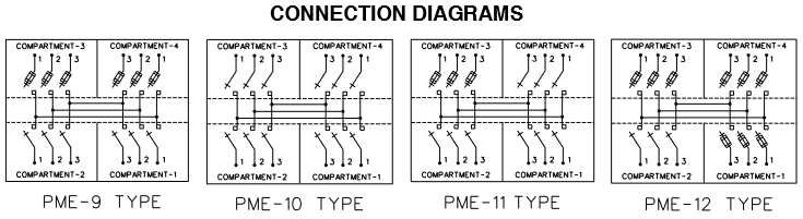
| D0550 | PME-9 | 2-3Ø 600A Disconnect Switch and 2-3Ø 200A Fused Switch | 1 | 1002410 |
| Fuseholder, SML-20 Dead-Front Switch Cabinet 200A 13.8kV | 6* | 1002493 | ||
| Padlock, P-Key 5/16" Stl Shackle, 7/8" W x 3/4" H Opening | 4 | 1000750 | ||
| Indicator, Fault, Adaptive Trip Sgl Phase 1.57"-2.37" Opening | 3 | 762379 | ||
| Indicator, Fault, Cable 3-Phase Fiber Optic 6' | 1 | 1001523 | ||
| Label, Information, "Fault Indicator" | 1 | 385824 | ||
| D0551 | PME-10 | 4-3Ø 600A Disconnect Switch | 1 | 1002466 |
| Padlock, P-Key 5/16" Stl Shackle, 7/8" W x 3/4" H Opening | 6 | 10000750 | ||
| Indicator, Fault, Adaptive Trip Sgl Phase 1.57"-2.37" Opening | 9 | 762379 | ||
| Indicator, Fault, Cable 3-Phase Fiber Optic 6' | 3 | 1001523 | ||
| Label, Information, "Fault Indicator" | 3 | 385824 | ||
| D0552 | PME-11 | 3-3Ø 600A Disconnect Switch and 1-3Ø 200A Fused Switch | 1 | 1002467 |
| Fuseholder, SML-20 Dead-Front Switch Cabinet 200A 13.8kV | 6* | 1002493 | ||
| Padlock, P-Key 5/16" Stl Shackle, 7/8" W x 3/4" H Opening | 5 | 1000750 | ||
| Indicator, Fault, Adaptive Trip Sgl Phase 1.57"-2.37" Opening | 6 | 762379 | ||
| Indicator, Fault, Cable 3-Phase Fiber Optic 6' | 2 | 1001523 | ||
| Label, Information, "Fault Indicator" | 2 | 385824 | ||
| D0553 | PME-12 | 1-3Ø 600A Disconnect Switch and 3-3Ø 200A Fused Switch | 1 | 1002468 |
| Fuseholder, SML-20 Dead-Front Switch Cabinet 200A 13.8kV | 6* | 1002493 | ||
| Padlock, P-Key 5/16" Stl Shackle, 7/8" W x 3/4" H Opening | 3 | 1000750 |
Notes:
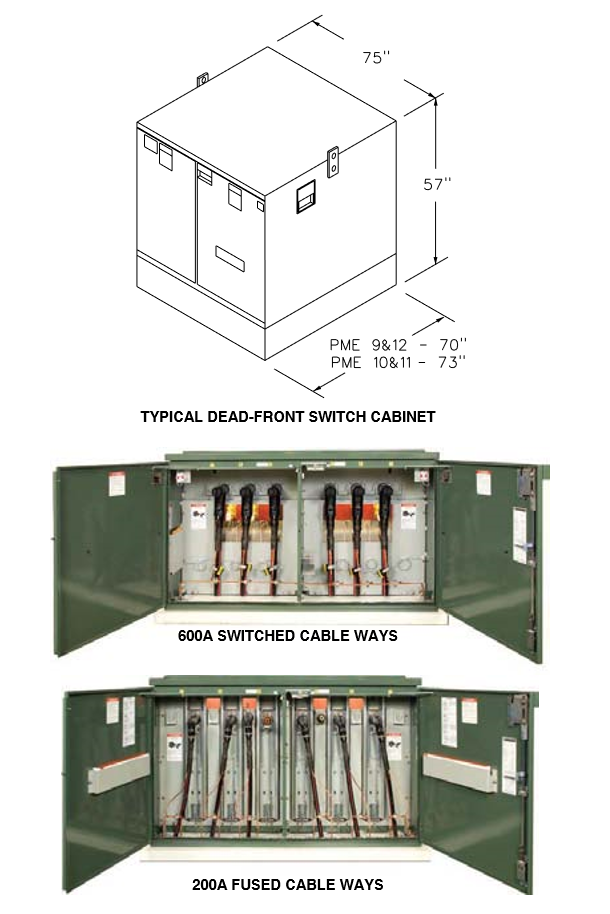
- Dead-front switch cabinets are preferred for new installations and maintenance replacement of live-front cabinets. Use live-front switch cabinets only when installation of dead-front switch cabinets is impractical.
Refer to Compatible Unit D0555 - D0558. - Cabinet dimensions shown in illustration are typical. Actual dimensions vary by manufacturer.
- For new installations place dead-front cabinets on vault Compatible Unit V0501.
- Dead-front switches come with a factory installed 12" base spacer. If additional ground clearance is needed, order a second 12" base spacer as follows:
PME 9 & 12 MID 1002506 PME 10 & 11 MID 1002507 - Refer to Compatible Unit E0551 for SML-20 fuseholders and SMU-20 fuse units. Note that spare fuseholders require fuses in order to be assembled and hung in the doors.
- Install 200A load-break elbows on fused cable ways and 600A dead-break elbows with 200A load-break inserts on switched cable ways. See Compatible Unit T1103 - T1110.
- Install 200A deadend caps on unused 200A bushings and 600A deadend caps on unused 600A bushings. See Compatible Unit T1701 & T1703.
- One padlock is required for each door latch and one for each switch-operating hub access cover. Required padlocks are included in each Compatible Unit.
- Fault indicator quantities issued with each switch are based on the assumption that all switch compartments will be utilized. If any switch positions will be unused, delete appropriate quantities of fault indicators, fiber optic indicator cables and fault indicator labels.
- Install fault indicators at each 600 amp switch position on each cable leaving the switch cabinet feeding load. To enable detecting fault indicator operation without opening the cabinet, for each set of 3 fault indicators install one 3-to-1 fiber optic cable. Each fiber optic cable is equipped with a lens which is to be installed through a ⁵⁄₁₆" hole drilled in the door of the pertinent compartment, approximately 12" below the upper outside corner of the door.
- Install a fault indicator label directly below the fiber optic cable fault indicator lens on the exterior of the door of each compartment containing fault indicators. Refer to Compatible Units W0135 - W0136 for additional information on fault indicator signage.