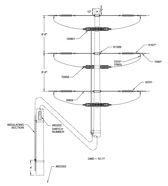
115V703 115kV Manually Operated -V- Switch
Revision 0
Jan 1, 1900
Notes:
- Mount two switches on road side of pole unless otherwise directed.
- When possible, mount distribution arm on same side of pole as switch control rod so climbing space will be unobstructed.
- Switch operating handle and control rod materials are included with "V" switch C.U. D0801.
- Refer to manufacturer's drawings for switch operating handle and control rod assembly detail.
- Line angles should be avoided on this structure.
- Refer to C.U. page W0202 - W0203 for MID numbers for individual number tags for switch numbering.
| Compatible Unit | Description | Quantity |
|---|---|---|
| D0801 | 115kV 1200A 3Ø Group-Operated Unitized Vertical Break Switch, 1 Pole Vertical | 1 |
| I0701 | Insulator, Polymer Suspension 115kV | 6 |
| I0904 | Insulator, Strain FG Clevis-Clevis w/ 1-Roller 30,000 lb. Ultimate Strength (Maintenance Only) |
6 |
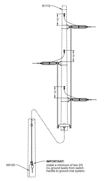
| N0105 | Mat System for Grounding Transmission Switch Controls | 1 |
| R107* | Clevis, Long Socket or Socket Eye | 6 |
| R1115 | Split Bolt Assembly, Pole Top 5/8" x 12" Machine Bolt | 1 |
| R1309 | Guy Hook, 2 Back-to-Back (3/4" x 18" Machine Bolts) | 3 |
| T060* | Deadend, Comp Sgl Tongue | 6 |
| T070* | Terminal, Comp 15° | 12 |
| T0955 | Bolt, SS 1/2" x 2-1/2" | 24 |
| T0956 | Bolt, SS 1/2" x 3" | 24 |
| W0202 | Holder, Vertical Al Substation Feeder Number 21" | 2 |