12F713 - Switch, 600A 15kV 3Ø Gang-Operated Switch
Revision 12
Nov 16, 2021
S&C 15kV Switch
(Preferred)
Notes:
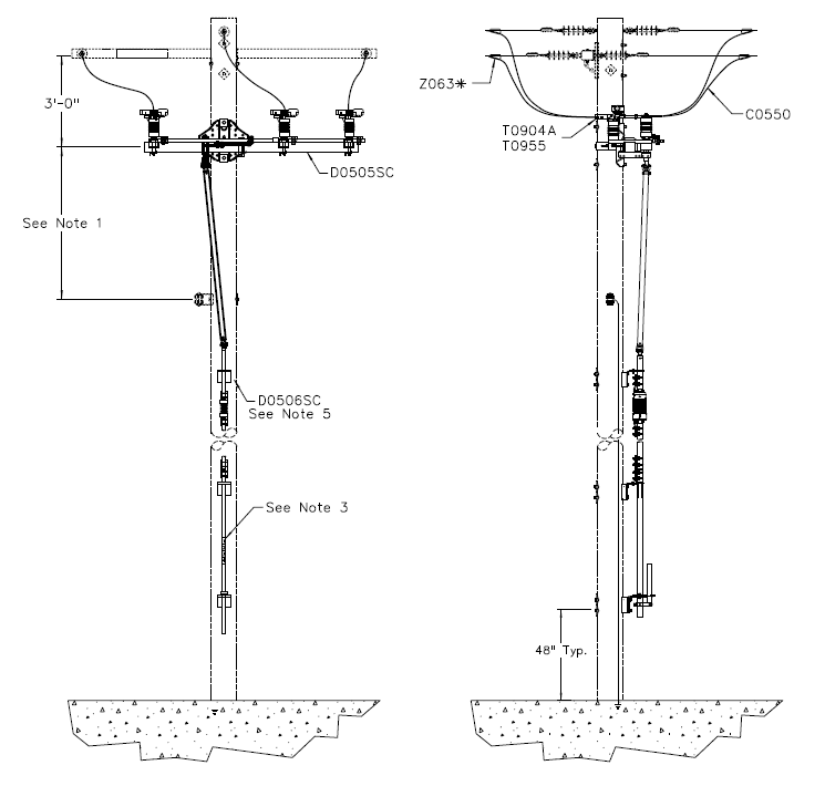
- Preferred spacing between switch arm and neutral is 5’-0”. Minimum allowable spacing is 4’-0”.
- Switch handle and operating rod may be positioned anywhere within 90° clockwise of the pole face. Switch handle and operating rod should be installed so as to minimize hazards to the operator and avoid conflicts with other pole mounted equipment.
- Using black and yellow reflective decals, stencil switch number on control rod directly above switch operating handle (MID 5001362 - 5001371). Using 1½" green and white reflective decals, stencil year switch was installed or last maintained, whichever is more recent, on control rod above switch number (MID 5001362 - 5001371).
- For fiberglass cross-arms, label switch numbers by applying 3" reflective decals with a yellow background (MID 5001182 - 5001202). For wood cross-arms, use Compatible Unit W0201 and 3" metallic tags.
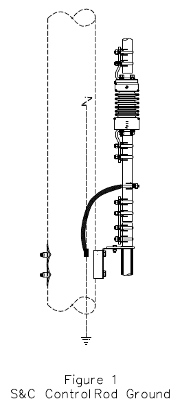
- Ground switch control rod and handle with single ground plate or ground rod. Refer to Compatible Unit N0101 or Compatible Unit N0110. Depending on switch type, connect switch control rod or switch control handle to ground wire as shown in switch grounding detail drawing.
- 90 degree terminal bar extensions available T0924-6
| Compatible Unit | Description | Quantity |
|---|---|---|
| C0550 | Tap Wire, Insul 4/0 Soft Drawn Copper | 36' |
| D0505SC | Switch, 600A 15kV 3Ø Group Op. (S&C Preferred) | 1 |
| T0700 | Terminal, Comp Straight 336.4 kcmil AAC | 6 |
| T0955 | Stainless Steel Bolt, 1/2” x 2-1/2” | 12 |
| W0201 | Holder, Plastic 15kV OH Switch Number 21" x 4" | 2 |
| Z063* | Connector, Wedge | 6 |