506743.1 15kV 600A Group Operated Unitized Load Break Switch
Click here for a PDF of this Material Standard
Revision 5
Aug 22, 2017
1. Scope
This Specification covers the requirements for furnishing and delivering horizontal crossarm mounted three-pole, unitized, group operated load break switches and accessories for use on a 60 Hz, 12.47 Grounded Y/7.2kV electrical distribution system.
3. Reference Standards
All characteristics, definitions, terminology, voltage designations and tests, except as otherwise specified herein, shall be in accordance with the following industry standards for distribution, power and regulating transformers. When the following standards are superseded by an approved revision, the revision shall apply.
Industry Standards
ANSI C37.32-2012 High-Voltage Switches, Bus Supports, and Accessories-Schedules of Preferred Ratings, Construction Guidelines and Specifications
IEEE 1247 IEEE Standard for Interrupter Switches for Alternating Current, Rated Above 1000V
District Standards
Material Standard 386202.1 2-1/4" Labels for Marking District Owned Equipment
Material Standard 890526.1 Padmount Equipment Danger Label
Material Standard 890534.1 Padmount Equipment Warning Label
4. General
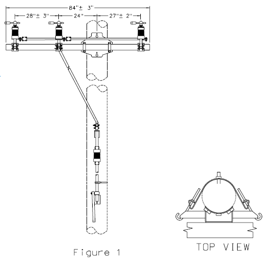
15kV 600A group operated unitized load break switches shall be factory assembled and designed for horizontal crossarm mounting on single pole structures. All three switch mechanisms shall be factory adjusted for proper alignment and simultaneous opening or closing.
Switches shall be capable of up to 50 feet of mounting distance between the control handle and switch mounting crossarm. The separation between the center phase switch and the center of the pole must be 24".
Refer to the Figure 1 for switch spacings.
5. Material ID Number
Material ID Description:
506743 Switch, 15kV 600A Group Operated Unitized Load Break Switch
6. Ratings
The switchgear shall have the following ratings:
| Power Frequency | 60 Hz |
| Nominal Voltage | 15kV |
| Maximum Voltage | 15.5kV |
| BIL | 110 kV |
| Max. Continuous Current. | 600 A |
| Short Circuit Current One-Second Short Time Withstand, RMS Symmetrical. |
25,000 A |
| Fault Close 2X Duty Cycle, RMS Symmetrica |
30,000 A |
| Load Interrupter | |
| Switches Continuous Current | 900 A |
| Interrupting Current | 900 A |
| Deadend Strength Ratings | |
| One Side per Conductor | 750 lb |
| Both Sides per Conductor | 8,000 lb |
At the District's request, the manufacturer shall furnish certified tests establishing the electrical ratings of the switch.
7 Components
7.1 Switches
Switches shall be side break integer style with field replaceable load interrupters. Switches shall be equipped with NEMA standard two hole terminal lugs. Terminal lugs and switch contacts shall be silver plated. Switches shall be capable of opening and closing under 3/8" ice formation.
7.2 Insulators
Switch mounting insulators shall be station post type, cycloaliphatic epoxy resin or silicone polymer. Porcelain insulators are not acceptable. Switches with torsional steel control rods shall be supplied with one 15kV class polymeric control rod insulator.
7.3 Crossarm
The switch shall be mounted on a pultruded fiberglass crossarm. The crossarm shall have a gray UV resistant coating and shall be filled with closed cell foam. Crossarm ends shall be sealed.
7.4 Mounting Hardware
The switch mounting crossarm shall be equipped with an integral brace-less gain base mounting plate, manufactured from heavy gauge galvanized steel or 6061-T6 extruded aluminum alloy. The mounting base shall include a metal mounting band for side-to-side adjustment of the switch assembly prior to final tightening of the mounting bolts (see Top View on previous page).
7.5 Operating Rods
Each switch shall be supplied with sufficient operating rod, guide bearings and couplings to allow installations with up to 36 feet of separation between the switch and control handle. Each section of control rod shall be a maximum of 10'-0" in length. Torsional control rods shall be 1-1/2" IPS galvanized steel pipe and shall include an insulated section of control rod. Reciprocating control rods shall be 1" OD fiberglass rod.
7.6 Operating Mechanism
The switch control handle shall have provisions for padlocking in the open and closed position. The control handle shall be equipped with a gained base for mounting to a curved surface and shall have provisions for alignment with the control rod after installation. Steel control rods shall include a flexible ground strap for grounding the operating handle and control rod.
8. Packaging
Each switch assembly, complete with switch, mounting hardware, operating rods and mechanism and instructions for installation, operation and maintenance of the switch shall be shipped in one crate.
9. Nameplate
A durable weatherproof and corrosion-proof metal nameplate shall be permanently and securely affixed to each switch by the manufacturer. It shall be permanently and indelibly marked with the following: manufacturer’s name and address, month/year of manufacture, manufacturer’s model or type designation, serial number, rated maximum voltage, BIL, continuous current, interrupting current, momentary (3 sec) current, and 10-cycle current.
10. Equipment Data Sheet
Each shipment of switches shall include a digital spreadsheet of all switches in the shipment and their nameplate data.
The spreadsheet shall be formatted to the District’s requirements shown below. Prior to delivery of the switches, the spreadsheet shall be emailed to the District’s Standards Department (standards2@snopud.com).
The following table describes the layout of the digital spreadsheet. Each column in the spreadsheet shall have a header with the field name and each row shall represent an individual piece of equipment. On request, the District will provide a template of the spreadsheet to the manufacturer.
| Column | Field Name | Data Type | Sample Date | Valid Values |
|---|---|---|---|---|
| 1 | Manufacturer Serial Number | Char(30) | JR102-2 | |
| 2* | Equipment Number | BLANK | BLANK | |
| 3 | Object Type | Char(10) | ED_SWITCH | ED_SWITCH |
| 4* | Start Up Date | BLANK | BLANK | |
| 5 | Manufacturer | Char(30) | S&C | |
| 6 | Model Number | Char(20) | 1037-418997-000 | |
| 7 | Manufacturer Part Number | Char(30) | 1765201303 | |
| 8 | Weight | Numeric(10,2) | 1213.1 | |
| 9 | Unit of Weight | Enum | LB | [LB, KG, TON] |
| 10 | Acquisition Value | Numeric(10,2) | 3000.02 | In USD |
| 11* | Acquisition Date | BLANK | BLANK | |
| 12 | Manufacturer Country | Char(2) | US | [US, MX, CA] - contact for others |
| 13 | Construction Year | Char(4) | 2017 | YYYY |
| 14 | Construction Month | Char(2) | 12 | MM |
| 15* | District Number | BLANK | BLANK | |
| 16 | MATERIAL_ID | Char(7) | 5000786 | PUD Internal Material ID |
| 17 | PURCH_ORDER_NUMBER | Char(10) | 4500014093 | PUD Purchase Order Number |
| 18 | PO_LINE_NUMBER | Char(2) | 1 | PUD Purchase Order Line Number |
| 19 | FLDAMPACITY | Numeric(8,2) | 600 | |
| *Column values must be blank and will be filled out by the District | ||||