N0106 Obsolete - Ground Layout Distribution Switch Controls
Revision 7
Jul 10, 2012
| Compatible Unit | Item | Description | Qty | Mid |
|---|---|---|---|---|
| N0101 | A | Staple, Galv 1-1/2" | 14 | 139144 |
| B | Connector, Mini-Wedge Al 3/0 to 2/0 | 1 | 212910 | |
| C | Connector, Wrench-Lok 2/0 Cu to 3/4” Rod | 2 | 213017 | |
| D | Connector, Split Bolt 2/0 Cu | 1 | 216409 | |
| E | Wire, 2/0 Cu Bare MHD 7-Str | 42' | 847915 | |
| F | Moulding, Ground Plastic 8’ | 1 | 892001 | |
| G | Rod, Ground 3/4” x 8’ | 2 | 902230 | |
| H | Staple, Ground Moulding | 6 | 905804 | |
| I | Tag, Grounding | 1 | 1001802 |
Notes:
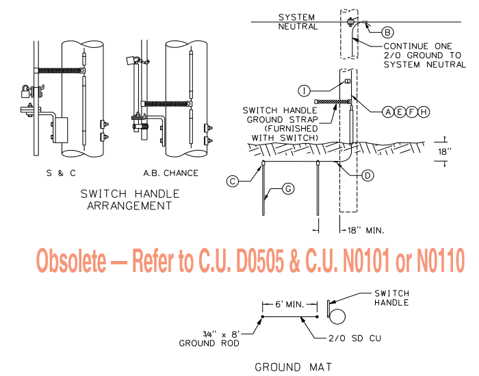
- Install grounding tag at eye level next to ground wire molding. This tag signifies the pole is grounded per NESC Article 094.
- Place the ground wire on the same side of the pole as the neutral conductor and in the quadrant outside of the climbing space. If the neutral is located in the primary position, extend ground wire moulding up through the supply space and connect to neutral as shown in Figure 1.
- Staple ground wire to pole every 6" for first 8' above ground. Staple ground wire every 2' from 8' above ground to neutral. Staple ground wire moulding every 1'.
- Ground plates are preferred for grounding new poles. Refer to Compatible Unit N0110.