Section 6 Generation Interconnection
Revised: Feb 21, 2025
A. Customer-Owned Generation
- Introduction:
Customers may request interconnection of generation projects for various purposes. The District will review each interconnection request using processes and criteria appropriate for the given project. In connecting generation of any type to the District’s electric system, the resulting system shall:- Ensure the safety of the general public and District personnel.
- Minimize possibility of damage to property.
- Minimize adverse service impacts to District customers.
- Minimize adverse electric system and operational impacts to the District.
- Adhere to District standards and operational requirements.
- Not cause adverse rate impacts to District customers.
- Permit safe and efficient operation of the generation project.
In addition, customers are urged not to purchase equipment or enter into any final purchase agreements until project requirements have been finalized and the District has reviewed and approved the project design.
Note: For purposes of this policy document, “customer” includes both current District customers served under one of its retail electric rate schedules and entities that are not currently District electric customers, but who intend to build generation in the District’s service territory. - Net Metering:
Net metering allows customers with certain types of small generating facilities to return electricity generated in excess of their immediate needs to the District for credit on their energy bill. Projects up to a total combined generation of 100 kilowatts at a site which use energy from solar, wind, water, biogas from animal waste, or combined heat and power technologies (including fuel cells) to generate electricity may be eligible to participate in the District’s Net Metering Program. Participating customers connect their generating equipment to, and operate in parallel with, the District's electrical distribution system and receive a credit on their bill for energy returned to the system.
The District uses a streamlined application process and standardized requirements for interconnection and net metering of inverter-based systems that have been certified to meet the standards of UL-1741. Refer to Section 6-B for details. If generation also provides emergency backup generation, the requirements of Standby Generation also apply. Applications must include existing generation at site and noted on one-line drawing of system. - Standby Generation & Batteries:
Standby, or emergency backup generation, which is intended to operate in parallel with the District’s electric system, will be evaluated on a case by case basis, and requirements identified which will minimize the likelihood of negative operational or safety impacts to the utility system.
Application for these interconnections is made using Form 6-1, Preliminary Application, or interconnection application. Refer to Section 6-C for details. Backup generation configured in a break before make connection will not require District approval or application. - All other Generation to be Interconnected to the District's Electrical System:
For all generation projects other than a single generator net metering or a standalone backup standby generation, the technical interconnection requirements will be based on the expected impact the project will have on the District electrical system. Requirements are project-specific, and are developed through District studies of the system.
Following an initial, high-level, Feasibility Review, more detailed studies may be required. These may include a System Impact Study and/or Interconnection Facilities Study. The District or its consultant performs these studies at the customer’s cost.
B. Net Metered Generation
- Introduction:
Projects up to 100 kW that use energy from solar, wind, water, biogas from animal waste, or combined heat and power (including fuel cells) may be eligible for net metering in accordance with state law (RCW 80.60). - Application:
Application for a net metered interconnection is made through the Customer Renewables group. These applications can be found on the District's website. - Technical Review:
The technical review is intended to ensure that the generation can connect safely to the District’s electrical system without negatively impacting service to other customers.
For single-phase projects connecting to single-phase transformers at secondary voltages through an inverter which is compliant with UL 1741, which require no modifications to the District’s electrical system, and for which total connected generation on the circuit is less than 15% of the circuit’s peak load, an expedited review and standardized technical requirements apply. Inverters must meet the UL 1741 without any additional devices, such as an auto transfer switch controller, for expedited review.
For projects not connecting through a UL 1741 inverter, for projects connecting at primary voltages, or for projects requiring modifications to the District’s electrical system, a more detailed technical review will be required. The technical review will consider the following:- Project capacity as compared to the service wire capability or the transformer nameplate;
- Imbalance created by connecting the generation to a center tap of a 240 Volt service;
- Total aggregated generation connected on the line section;
- Total aggregated generation connected on the circuit; and
- Existing and proposed available short circuit current at the point on the District feeder where the generation is to connect.
- Technical Requirements:
In order to comply with State worker safety laws, the ability to provide a disconnect located electrically between the generation equipment and the District’s electrical system must be available. This can be achieved by a District socket type meter that is 320 A or less, or a disconnect switch. For CT connected meters, and all meters greater than 400 A, a customer owned disconnect switch will be required. Guidelines for placement of the switch are described in the NEC code.
Note: Projects 78 kW and greater must be three-phase.
For all projects, the District metering must be modified in order to credit the customer’s account for energy delivered to the District, and if applicable, accurately track production of electricity for State incentive programs.
The customer must provide a certificate of completion showing inspection of the system by the electrical inspector having jurisdiction over the installation. - Standardized Technical Requirements for Small Net-Metered Systems:
For projects up to 77 kW, connecting to single-phase transformers at secondary voltages of 120/240 volts, through a self-contained meter, and for which total connected generation on the circuit is less than 15% of the circuit’s peak load, an inverter, or whole home control device with integrated inverter, which is compliant with UL 1741 specifications satisfies the protective equipment requirement.
Where standardized requirements do not apply, technical requirements specific to the project will be issued by the District’s System Planning and Protection Department. - Agreements:
In addition to any agreements regarding District financing or incentives, a Net Metering Agreement must be completed before the project is initially energized.
An Interconnection Agreement must be executed. This outlines the interconnection requirements, billing and revenue agreements, and ongoing maintenance and operation requirements. - Operation:
When required for District line work, the generation will be disconnected. If the work is planned, the District will make efforts to provide advance notice. For emergency conditions, no advance notice can be given. - Sample Documents:
Sample documents can be found at:- Net Metering Agreement, Interconnection Application.
C. Standby Generation Connections to the District's System
- Introduction:
Emergency generation as covered in NEC Articles 700 through 705 may be connected to customer load by utilizing either an open transition transfer switch or a closed transition transfer switch. Typically, backup generation is provided using synchronous rotating machines.Alternatively, inverter based resources like batteries may provide backup power.
Any generation which will operate in parallel with the District’s electrical system has the potential to impact safe operation of the system and service to other customers. All projects will be evaluated to determine the extent of the possible impacts and identify project requirements to minimize the probability of adverse effects. - Application:
Customers should submit Form 6-1, Preliminary Application for Operation of Customer-Owned Generation well in advance of project initiation. Generator and transfer switch information are provided on this form and are used by District personnel in identifying project parameters. However, backup power that is connected through a UL1741 certified devices should submit an interconnection application.
It is especially important to note whether the transition switch is capable of operating with both positions closed, so that the generation operates in parallel with the District’s electrical system, and for how long the parallel is designed to last. An electrical one-line diagram showing connection to the District electrical system should also be included with the application.
Customers proposing to operate generation in parallel with the District electrical system should submit their final application using Form 6-2, Final Application for Operation of Customer-Owned Generation.
The District will use information from the application to model the generation at the District circuit to which it connects so that the electrical performance can be evaluated. Characteristics of the transfer switch are also important. While operation as intended generally does not cause system disturbances, the consequences of other modes of operation must also be considered. Failure of a single device shall not result in loss of protection for a system. - Technical Review:
District customers may use a closed transition transfer switch in a make before break mode to momentarily parallel an emergency generator to the District’s electric system when the District’s electric system is also energized. Closed transition switching shifts load between an emergency generator and the District system without dropping load.
Closed transition switching is normally used for periodic emergency generator testing or after the District has restored electric service subsequent to an outage. The closed transition transfer switch must meet specific requirements.
The technical review will consider the operational modes available and proposed for the transfer switch. If the generation will be connected through a make before break transfer switch, paralleling the generation with the District system, it may be necessary to provide relays to detect an inadvertent extended period of parallel operation. - Technical Requirements:
The District will provide interconnection technical requirements for each project, which must be incorporated into the system design.
Generation connecting through a closed-transition transfer switch must meet the following requirements unless connected through a UL 1741 certified devices:- The closed transition transfer switch must be UL/ANSI Standard 1008 listed, and must be labeled as such.
- The installation and operation of the closed transition transfer switch and the emergency generator shall comply with NEC Articles 700-705.
- The closed transition transfer switch shall function in the closed transition mode only when the District source and the backup generation source are energized and in synchronism. For all other transfers, the switch must operate in a break before make mode.
- If the closed transition, make before break, transfer mode is intended to parallel the District electric system with the backup generation system for more than 100 milliseconds, or if the aggregate generation is 1 MW or greater, protection must be provided to disconnect the generation system in the event of a fault on the District electric system.
- The closed transition, make before break, transfer mode must be supervised and controlled by a customer owned synchronism check relay and the transfer shall take place only when both the District source and the backup generation source are within 5% of each other in voltage, within 0.2 Hz in frequency, and within five electrical degrees in phase.
- The normal operation of the closed transition transfer switch shall not cause objectionable electrical disturbances external to the customer, as determined by the District.
- The customer will be responsible for the protection of its facilities from any voltage or frequency excursions that occur on the District system. This includes any voltage and frequency excursions that occur during the closed transition transfer.
- A District-owned visible disconnect switch will be installed at all points of interconnection to the District system at the customer’s expense. The disconnect switch(es) shall be equipped with a lockable mechanism for clearance tagging to provide a visible air gap to ensure isolation of the customer generators from the District system.
Customers must provide documentation showing equipment installed to meet the requirements along with their final application (Form 6-2). This includes but is not limited to:- Final electrical one-line diagram
- Equipment parameters and ratings
- AC and DC schematic drawings
- Three-line diagrams showing protective devices and their control outputs
- Spec sheets for all installed equipment (Modules, inverter, controller, combiner, battery, etc.)
- Any pertinent information regarding normal operating modes
- Relay styles and part numbers
- Relay settings proposed
- Test plan
- Design:
Once the District provides interconnection technical requirements for the project, the customer may proceed with design of the project.
Before equipment is purchased and construction begins, the District will review the customer’s final interconnection design to verify that operation will be as intended. The review will encompass the following customer documents:Detailed one-line diagram of the entire Generating Facility
This drawing shows the functional arrangement of all interconnection and generation equipment, and must include a table showing equipment ratings.
AC current and potential schematic of the Generating Facility
The AC schematic is a primary three-line drawing showing the phasing and interconnection of the current and voltage transformers with the interconnection protective relays. The drawings should show all grounding of equipment and should indicate polarity.
A control schematic of the Generating Facility
The schematic shall be functionally complete, showing all DC potential circuits with all relays and control connections to the tripping and closing coils of the interconnection breaker. Please include a contact development table for all interconnection relays and control switches used in control of the interconnection breaker.
Equipment specifications and details
This should include the specifications and details for transformers, circuit breakers, current transformers, voltage transformers, and any other major equipment. Transformer information should include configuration, ratings, nameplate diagram, and percent positive- and zero-sequence impedance based on the transformer’s self-cooled rating. In addition, please provide model and style number for all interconnection protection relays.
- Agreements: An Interconnection Agreement must be executed. This outlines the interconnection requirements and ongoing maintenance and operation requirements.
- Witness Testing Upon District Request: Prior to system commissioning, operation of any required protective devices must be demonstrated to District representatives. The customer must submit a test plan outlining procedures and expected results for use during the witness testing.
- Operation: When required for District line work, the generator will be disconnected. If the work is planned, the District will make efforts to provide advance notice. For emergency conditions, no advance notice can be given.
- Sample Documents:
D. All other Generation to be Interconnected to the District's System
- Introduction:
The District will evaluate all generation projects designed to operate normally in parallel with the District’s system, whether the customer intends to sell the output to the District or not, based on the generator’s expected impacts to the electric system.
For projects with a nameplate capacity greater than or equal to 200kW, Bonneville Power Administration (BPA), which acts as the Balancing Area Authority for the District, requires the project owner/operator to submit a separate interconnection request and to enter into a Balancing Authority Area Services Agreement or BAASA. The aggregated total generation on the site includes all sources of power, including batteries.
BPA will evaluate whether additional deposits and technical studies must be performed, and will determine whether additional technical requirements, metering, integration services, agreements and/or fees apply. Detailed information on how to submit an interconnection request and the BAASA is available through BPA’s Interconnection Home Page.
The District can facilitate an introductory meeting to help the customer initiate the BPA process. Note that BPA requirements are separate from, and in addition to, the District interconnection process and requirements identified below.
For projects meeting all of the following criteria, expedited processes and more standardized requirements apply:- The project does not qualify for net metering
- Capacity of the proposed project is less than 500 kW
- The proposed connection is to a radial distribution circuit
- If the project connects through an inverter, the inverter is UL 1741 certified
- The generator is not a synchronous generator
- The generation does not exceed the lesser of the service wire capability or the nameplate of the transformer if proposed for connection to a shared secondary
- If connected to the center tap of a 240 V service, the generation does not create an imbalance between the two sides of the 240 V service of more than 5 kVA
- The aggregate nameplate capacity of all generation on the line section where the generation connects must be less than 15% of the line section’s annual peak load
- • Only minor upgrades to the District electrical system (<$10,000) are required to interconnect the project
- The short-circuit current contribution of all the generation on the circuit does not exceed 10% of the distribution circuit’s maximum available fault current at the primary distribution level nearest where the generation connects
- Maximum available short circuit current on the circuit proposed for connection does not exceed 87.5% of the interrupting capability of any District protective device or equipment
- Application:
Customers should complete and submit Form 6-1, Preliminary Application for Operation of Customer-Owned Generation to the District to indicate interest in installing generation connected to the District’s system. In addition, the customer should include an electrical one-line diagram showing basic service voltages, anticipated metering location, desired point of interconnection, major facility equipment and ratings, and any pertinent information on normal operating modes and proposed in-service dates. - Technical Review:
The District performs a technical review to identify equipment and/or operational practices needed to ensure safe, reliable operation of the project that meets the needs of both the customer and the District. Computer simulations of the existing District electrical system are used to analyze such project parameters as voltage regulation and reactive power capability of the generator, as well as short-circuit contribution, ability to detect and clear for faults and abnormalities, and the likelihood of operation in an inadvertent island mode with other District customers.
The District performs different types of studies as described below, which become increasingly detailed as additional information becomes available and as the likelihood of connecting the project increases. - Study:
The District performs studies at various stages of project development. Each study provides specific types of information, with increasing levels of detail included as projects progress. While all studies will likely be required for larger projects, it is the customer’s option whether to proceed through each study, with the opportunity to make decisions to proceed based on study results, or to combine studies in an effort to reduce the overall time required for completion of the studies.- Feasibility Review
After receiving a preliminary application (Form 6-1), the District will perform a high-level review of the proposed project to identify basic parameters of the interconnection, to determine which processes and technical requirements apply, and to provide a description of potential technical requirements for the project, along with a non-binding outline of equipment and work which may be needed. Factors reviewed in this feasibility review will include such characteristics as availability of three-phase service at the project site if required, circuit load capacity, annual circuit and/or line section peak and minimum loads, available short-circuit current, any existing system constraints, and protective devices affected by the proposed installation. The District contact will schedule a meeting with the customer to present and discuss the findings of the feasibility review.
An initial feasibility review is performed as a courtesy to District customers at no charge. If significant revisions are proposed to a project already proposed, a fee may be required to cover District costs to re-study the project. - System Impact Study
If the customer elects to proceed with the project based on the results of the feasibility review, the District will perform a System Impact Study (SIS). Because the District personnel time and resources required to complete this study can be significant, the customer must sign a System Impact Study Agreement and pay a fee to cover District costs to perform the study.
To provide the District with the data needed for the system models, the customer must submit a Final Application for Operation of Customer-Owned Generation (Form 6-2) along with additional information pertaining to equipment characteristics.
The SIS identifies detailed effects to be expected due to operation of the generation, and includes such analysis as power flow and short-circuit studies, and stability modeling as needed. The SIS will also provide a high level summary of technical requirements that may apply for the interconnection. - Interconnection Facilities Study
Following acceptance of the SIS, the customer may elect to request an Interconnection Facilities Study (IFS). The IFS will identify technical requirements that apply for interconnection, which may include the voltage operating range and reactive power requirements for the generator, along with the need for installation of a Power System Stabilizer to meet WECC operating criteria.
In addition, any mitigating measures required to ensure ability to detect and clear for all faults, alleviate system overloads or increases in available short-circuit current caused by the generation, and prevent the project from islanding unintentionally with District loads will be identified.
The report will also provide detailed estimates for the work identified in the SIS which is required on the District’s electrical system for the interconnection, as well as an estimate of the timeline for completing the work. The customer must sign an Interconnection Facilities Study agreement and pay a fee to cover District costs to perform the study.
Customers who have a high degree of certainty of implementing a project may choose to combine the SIS and the IFS into a single study. This can reduce the total time required for the District to complete its portion of the study phase of the project.
- Feasibility Review
- Design:
Design of the interconnection must be performed by a professional engineer licensed in the state of Washington.
Once the District and the customer execute an Interconnection Agreement, design efforts may commence in accordance with the milestones identified in the agreement. Milestones will include the District providing detailed interconnection technical requirements for the project, the customer’s design efforts and purchase of long-lead time equipment, and the District’s design of any required modifications to the District’s electrical system. The customer and the District must agree on the milestones before the Interconnection Agreement is signed.
Prior to purchase of equipment and start of construction, the District will review the design of the interconnection to verify that operation will be as intended. The review will encompass, at a minimum, the following customer documents:- Detailed one-line diagram of the entire Generating Facility
- AC current and potential schematic of the Generating Facility
- A DC control schematic of the Generating Facility
- All electrical drawings must be stamped by a professional engineer
- Ground mat design and test data
- Equipment specifications and details
The System Protection Group performs relay setting review as the final step in the technical review. This review is intended to ensure proper clearing as required for all faults on the District electric system, as well as coordination with District protective devices. - Construction:
The customer and the District will proceed with construction efforts in accordance with the milestones identified in the Interconnection Agreement. The District will complete required improvements to the District electrical system identified in the IFS. - Protective Relay Testing:
Calibration testing of the required interconnection relays must be performed by a qualified test firm, and signed copies of the test reports provided to the District prior to witness testing.
When all necessary improvements to the District electric system are complete and the generation facility is complete, District representatives will witness operation of the required interconnection relays. In advance of the witness testing, the customer must provide a test plan for demonstrating operation of the required interconnection protective scheme. This shall include a step by step checklist for all required protective functions with a list of expected outcomes.
The District may ask to witness initial parallel operation of the generation facility. - Agreements:
Before the generating facility is allowed to start commercial operation, all required agreements must be completed and signed by both the customer and the District, and witness testing completed, and a letter from the District authorizing parallel operation. These may include an Interconnection Agreement and a Power Purchase Agreement or Aggregation and Redelivery Agreement. The customer must also provide the District with proof of all agreements executed with BPA or other utility or purchaser of the plant output.
From time to time, consistent with the terms of the Interconnection Agreement, the interconnection protection package may be reviewed to ensure that it meets the technical interconnection requirements currently in effect. Any plant revisions made necessary because of changes in technical requirements must be made at the customer’s expense. - Operation:
The Interconnection Agreement identifies operating requirements for the project. Notice must be provided to the District according to the provisions of the Interconnection Agreement for any changes made to (i) the project to comply with changes in operating requirements, or applicable laws and regulations, or (ii) the point of contact for the operation and maintenance of the project. - Sample Documents:
ESR Manual: Section 6 - Form 6-1 Preliminary Application for Generation
ESR Manual: Section 6 - Form 6-2 Final Application for Generation Interconnection
Facility Connection Requirements
Sample System Impact Study
Sample Interconnection Facilities Study agreement
Sample Interconnection Agreement
Sample Power Purchase Agreement
Exhibit 1: Interconnection Process Flow
E. Solar Net Meter Generation
Installation of Solar Generation Production Metering must comply with the requirements in the District's Electrical Service Requirements Manual (ESR) as well as the requirements of the local electrical jurisdiction and the State of Washington.
Meters shall be permanently labeled "Production Meter" and "Net Meter" in compliance with ESR, Section 5-F. Service Identification/Meter Labeling.
Preferred location of meters shall be adjoining as shown on the figure below when possible. If adjoining meter locations are not possible meters shall be in clear view with unobstructed safe access of each other.
Contact the District's Energy Services Department for further information.
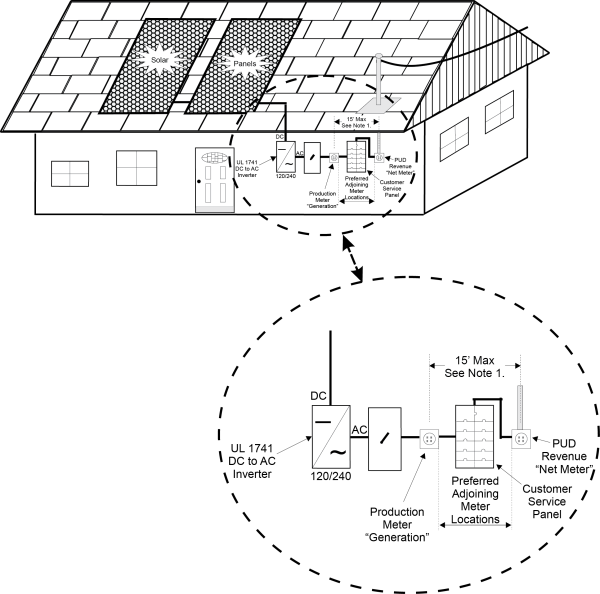
- Preferred location for District revenue meter is within 15' of production mater. Greater distances may be acceptable with prior District approval before installation.
- Production meter is for the Washington State Renewable Energy Production Incentive. Production meters are no longer required by the District. If installing a production meter, it must be labeled on the one-line as customer owned.