Section 5 Meters and Service Entrance Equipment
Revised: Jan 20, 2026
A. General
- The customer shall be required to supply, install and maintain meter mounting equipment of a type acceptable to the District.
- The District must approve all meter locations prior to installation (WAC 296-46B-230).
- Where multiple meter bases serving the same address or where confusion could exist which meter serves what, such as apartment houses, commercial businesses, solar generation and other situations all meter bases shall be permanently labeled as specified in Section 5-F.
- Metering shall not be mounted on District poles, District padmount transformers or transclosures.
- No customer owned equipment may be installed between the meter-mounting equipment and a District meter.
- In the case of a meter room or switchgear in an electrical room unmetered service conductors are only allowed to enter the building once, at the metering point.
- The District will furnish meters, meter retaining rings, current transformers and associated metering equipment, exclusive of mounting brackets, hardware or enclosures.
- The customer shall provide sufficient space and exercise proper care to protect District property on his premises. In the event of loss or damage to District property on the customer’s premises arising from neglect, carelessness or misuse, the cost of necessary repairs or replacement will be billed to the customer.
- Energizing The Service:
When a PUD representative arrives to initially connect a new service, they must have access to the main disconnect in order for service to be energized.
-
Meter Seals
- At the time of installation, the meter base (socket), enclosures and or raceways containing unmetered conductors or bus bars shall be sealed and shall not be tampered with nor shall the seal be broken by anyone without prior authorization from the District. Any tampering with the meter or unauthorized breaking of seals shall be considered an evidence of fraud (RCW 80.28.240).
- “All District seals shall be readily visible without having to open or remove any covers or panels" (See Figure 5‑1 for seal types and uses).
- All current transformer metered services 801 amps and above shall be installed in switchboards. Refer to Section 5-O.
- The customer or his contractor shall connect their equipment to keep the load, under normal operating conditions, balanced within plus or minus 10% of the average load across the phase wires.
-
Service entrance equipment shall be arranged such that metered circuit conductors or bus bar do not enter or pass through the conduits, raceways or enclosures containing unmetered circuit conductors or bus bar.
Exception: That portion of service load side conductors or bus bars exiting the meter socket or current transformer enclosure. - Power conductors are not allowed in current transformer metering wire conduits.
- Devices installed on the District side of the meter are prohibited. This includes between the meter and meter base. Examples include, but are not limited to: Electric vehicle chargers, backup generation transfer switches, emergency disconnects and surge protectors.
- Underground service meter bases with sheetmetal channels or raceways passing through the load center or breaker compartment are not approved due to the risk of damaging the service conductors or the meter base itself during the installation of conductors.
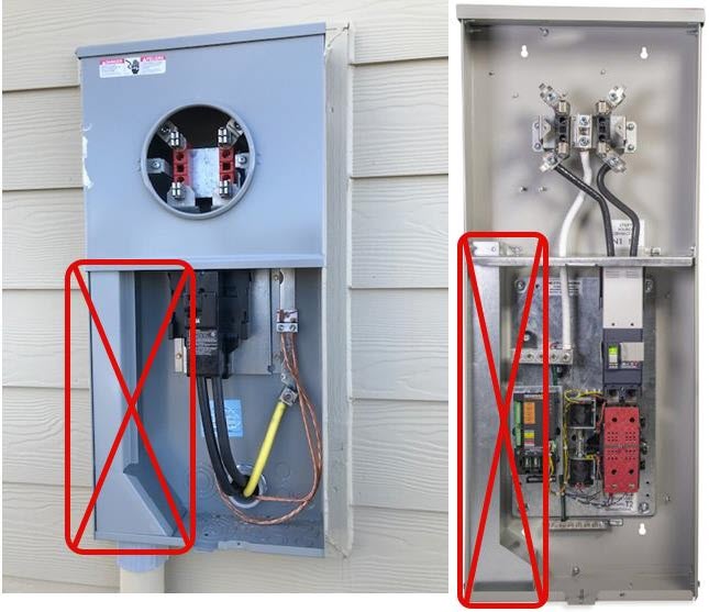
Meter bases with separate lockable cable compartments are approved.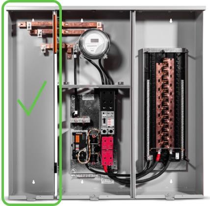
B. Meter Totalizing
- As a general practice the District will not totalize meters for billing purposes. Meters will not be totalized to aggregate loads in an attempt to seek advantage of District rate schedules. If it is determined by the District that totalizing meters for billing is beneficial in order for the District to serve customer loads the District would consider only for services requiring transformation greater than 2500 kVA and/or, due to customer load requirements. The customer's electrical design will not be a determining factor when considering totalizing.
- In all above applications the preferred method of service to accommodate the above mentioned requirements will be from a 12,470 kV primary metered service. Otherwise, when multiple meters are used for one service, individual billing will be issued for each meter.
- Any consideration for meter totalizing must be reviewed by District management through the variance process currently established by the District. Refer to Section 2-U.
C. Sequence of Service Entrance Equipment
-
Self-contained service equipment 200 amps or less
The sequence of service equipment for services metered with a socket type meter, and not requiring current transformers, shall be meter - switch, fuse or circuit breaker - load; refer to Figure 5-2, Figure 5-3, Figure 5-4 and Figure 5-5. See Section 5.A.15 for a list of prohibited devices.
-
Over 600 volts - primary metered.
For requirements, contact the District. -
Instrument metered service equipment 201 to 800 amps
The sequence of service equipment for services metered with current transformers and/or potential transformers shall be instrument transformers with associated meter-switch-fuse-load except on switchboards designed with a main circuit breaker with sub-feed breakers to more than one customer. Refer to Figure 5-6 , Figure 5-7 and Figure 5-8.
District Meter Seals
Demand Meter Reset Seal

Black plastic meter seal used after resetting demand metering.
Note:
- Each plastic seal has a unique serial number.
Figure 5-1: Plastic Seals

Seals are color coded to distinguish self contained meters, (a) where load side is dead when meter is removed from the metering socket and instrument metering, (b) when the load side is hot when meter is removed from the metering socket.
Color Code:
- Clear/Green - Self contained metering. Service active and normal.
- Clear/Orange - Instrument Metering. Service active and normal.
- Clear/Yellow - Meter disconnected.
Note:
- Each plastic seal has a unique serial number.
Figure 5-2: 1Ø Service Entrance Equipment Self-Contained (240/120 Volt 3-Wire Single Phase)
")
- 18" Leads Minimum
- Neutral shall be identified with white or gray tape
- 4 terminal meter socket
- Mounting Height 4' minimum to 6' maximum
- Neutral bonded in meter socket Code white or gray
- Commercial installations require safety socket or link by-pass
- Ground per NEC
Figure 5-3: 480 Volt 3-Wire 1Ø

- 18" Leads Minimum
- Neutral shall be identified with white or gray tape
- Mounting Height 4' minimum to 6' maximum
- Neutral bonded in meter socket Code white or gray
- Commercial installations require safety socket
- Ground per NEC
Figure 5-4: 3Ø Service Entrance Equipment Self-Contained - Wye
208/120 Volt 4-Wire 3Ø Wye
480/277 Volt 4-Wire 3Ø Wye

Note - Conductor Color Coding: Each service conductor shall be durably and permanently marked by an outer finish at each termination or junction point as follows. 3Ø Wye: White, Blue, Black, Red
- 18" Leads Minimum. 3/0 Cu or 4/0 Aluminum Minimum
- Neutral shall be identified with white or gray tape
- 7 terminal meter socket
- Mounting Height 4' minimum to 6' maximum
- Neutral bonded in meter socket Code white or gray
- All installations require safety socket
- Ground per NEC
Figure 5-5: 3Ø Service Entrance Equipment Self-Contained - Delta
120/240 Volt 4-Wire 3Ø Delta
240/480 Volt 4-Wire 3Ø Delta

Note - Conductor Color Coding: Each service conductor shall be durably and permanently marked by an outer finish at each termination or junction point as follows. 3Ø Wye: White, Blue, Black, Red
- 18" Leads Minimum
- Neutral shall be identified with white or gray tape
- 7 terminal meter socket
- Mounting Height 4' minimum to 6' maximum
- Neutral bonded in meter socket Code white or gray
- All installations require safety socket
- Ground per NEC
Figure 5-6: Overhead 1Ø Current Transformer Enclosure

Note: The District will furnish, install and wire the current transformers. The District will also make metering connection and final service connection at the weatherhead. For current transformer rated 480V single phase, the District may install a voltage transformer.
Figure 5-7: Underground 1Ø Current Transformer Enclosure

Note: The District will furnish, install and wire the current transformers. The District will also make metering connection and final service connection at the weatherhead. For current transformer rated 480V single phase, the District may install a voltage transformer.
Figure 5-8: Overhead 3Ø Current Transformer Enclosure (3Ø Wye or 3Ø Delta)
")
Note: The District will furnish, install and wire the current transformers. The District will also make metering connection and final service connection at the weatherhead. For current transformer rated 480V single phase, the District may install a voltage transformer.
D. Meter Locations
- The number of meter locations on any single structure will be determined by the number of service strike locations to the structure. Refer to Section 2-B.4.
- Where there is more than one service point location permitted (by any exception), a permanent plaque or directory shall be installed at each service drop or lateral or at each service-equipment location denoting all other services on or in that building or structure and the area served by each.
- The customer shall furnish a single location on the outside lines of a building with direct and safe access acceptable to the District, readily accessible without risk of bodily harm to District employees, free from vibration, corrosive atmosphere and abnormal temperatures in which to install the metering equipment. The equipment shall be protected from damage (WAC 296-46B-230). A 36-inch minimum clearance must be maintained from gas meters, propane tanks or piping.
- Meters shall not be located in carports, breezeways, porches or similar locations. Meters shall not be located where it is required to access the meter by going through interior lines of a building such as breezeways, carports, parking garages etc.
- The preferred location of any metered service shall be at a distance greater than 25 feet from railroad tracks.
- Service locations – Mobile Home / Recreational Vehicle
- Permanent safe walking access shall be provided and maintained by the customer to meter poles or meter pedestals that have District equipment on them, i.e. meter and service wires. Refer to Section 2-O.
- When a meter pedestal is located in a parking area, it must be located and protected so that parked vehicles will not restrict meter accessibility or allow the pedestal to be damaged by vehicular traffic. Guard posts may be required for protection. Refer to Figure 4-15.
- Disconnect shall be located per approving authority.
- Installation of six meters or less shall be on the outside lines of a building and shall be grouped in such a manner that a single service run will serve all meters.
- Meters shall not be installed in commercial buildings above the first level or below the first basement level without prior District approval.
- The number of meter centers in multiple floor buildings shall not exceed "one" for three floors, without District approval.
- Installation of seven meters or more may be inside the lines of a structure provided the location is a dedicated metering room accessible to the District in accordance with the definition in the Glossary, in compliance with Section 5-D and with reference to Figure 5-11.
- A meter installed in an alley, driveway, or walkway must be recessed in the wall (Refer to Figure 5-9) or protected adequately with guard posts to prevent damage from vehicular traffic, or impede pedestrian traffic.
Figure 5-9 Recessed Meter Clearances

Notes:- Opening must extend a minimum of 3' around the meter enclosure
- Depth must not exceed 9"
- All meters shall be readily removable, i.e. not plastered in or built in
- The meter recessed opening shall be as shown with the socket centered therein
- "Ring type meter base required"
- Doors over meters are not allowed
Figure 5-10: Meter Cabinet Enclosure

Notes:- Opening must extend a minimum of 3" around the meter enclosure
- Depth must not exceed 10"
- Access door and cabinet shall be maintained by the Customer
- Access door shall...
- be side-hinged
- open at least 90 degrees
- remain unlocked by Customer to allow access at all times
- be permanently labeled "ELECTRIC METER"
E. Meter Rooms
- A minimum of seven or more active metered services are required before a meter room will be allowed.
- The required BEST lockset must be installed on the meter room door and a unit verification be completed before the billing of the meters will be taken out of the owner/contractors name.
- Permanent labeling of service identification is required. Refer to Sections 2-F. and Section 5-F.
- When a metering room is requested, a floor plan shall be submitted to the District for approval in the design stage and prior to any construction or wiring (WAC 296-46B-230).
- The meter room shall be dedicated and secured for electrical equipment and never used for storage.
- The meter room shall not be installed above or below the ground level of the building and shall be accessible through a single exterior door on the exterior lines of the building.
- Safe access must be provided to the exterior door without having to enter or go through such areas as parking garages, hallways, breezeways, stairways or other such interior building lines.
Exception: When reviewed and approved in advance of final design and construction, a meter room may be allowed on the ground floor in the parking garage of a large commercial structure such as an apartment building or condominium if it complies with the following requirements:- The egress into the parking garage is at the ground level elevation through an exterior man-door or roll up door, and the required BEST knobset or BEST electromechanical switch is located on or near the access door keyed with a different “SP” tumbler series core than used for the Meter Room door.
- There is a phenolic sign in accordance with Section 5.F. permanently attached to or next to the exterior entrance indicating “PUD Electrical Room Inside”.
- The meter room door is in compliance with 5.E.8. (below) and that the “SP” core shall have a different tumbler series core than the exterior access door with a limited amount of keys so that tenants do not have the ability to enter the meter room.
- Access by District employees to all other interior areas of the building, including elevators and interior stairways, is restricted by use of locking knobsets or electronic card key passage.
- Meter Rooms shall be secured according to the following requirements:
- Location: The access to the Meter Room shall be from the exterior ground level lines of the building via a minimum 2’8" x 6’8" solid core or steel door. Doors shall include a latch guard plate.
- Knobset: Heavy duty BEST knobset (Series #83K7D4D_ 626 SPN, or Series #93K7D15D _ 626LM) from BEST Access Systems.
Note: The use of a key box is not acceptable. - Panic Bar: In the event a panic bar device and/or a door closure is installed a heavy duty panic bar exit device (Precision 5100 or 5200 series in 603, 703A or 808A trim) and heavy duty automatic door closure (Stanley No. HD8016 or Stanley QDC211 F 689) is required.
Note: Panic bar and automatic door closures from alternate manufacturers are not acceptable. - Locking System: After the installation of knobset or panic bar, a locking system shall be furnished and keyed with an "SP" tumbler series core which will accept the District's master key. The locking system shall not allow common access to unauthorized individuals. To purchase the required locking system, please contact:
Everett Safe and Lock & A-1 Mobile Lock and Key
5108 Evergreen Way, Ste 3
Everett, WA 98203
pudlocks@everettsafeandlock.com
Phone: 425-258-1422Puget Sound Hardware
4710 B St NW, Ste 105
Auburn, WA 98001
Attn: Niki Eklof
800-464-4801 Ext 102
- The owner and his/her agents and/or the homeowners association of the building shall be responsible to install, retain and maintain the District's required BEST knobset and passage key system for the life of the service to the premises or the electrical service to the building will be subject to disconnection.
- The customer/owner shall furnish and install and maintain a permanent sign on the exterior door stating "Electrical Room" and provide building identification in multiple unit complexes.
- The customer/owner shall agree to allow the District to furnish and install an "Electrical Room" sign on the interior surface of the Meter Room door and shall further agree to allow this sign to remain clearly legible without removing, covering or painting over the sign for the life of the service to the premises.
- Telephone and Cablevision terminal equipment may occupy this room provided they do not interfere with the electrical equipment, and each shall have its own provision for access.
- The room shall be illuminated by permanent fixture(s) with a switch inside next to the latch side of the door, with a minimum of 10 foot candles per square foot.
- The access door shall be installed such that it will not make contact with the meters or other electrical equipment.
- Water, gas, sewer and drain pipes shall not terminate or pass through this room (sprinkler systems required by building codes are exempt).
- Proper drainage will be required when there is a possibility of standing water.
- The room shall have a 2' x 2' 3/4" sheet of plywood installed on the wall for the exclusive use of District equipment. The plywood shall be permanently labeled "PUD Use Only". The plywood shall be mounted a minimum of 4' and a maximum of 6' above the floor. There shall be a 120V 15A duplex outlet below the plywood for use in powering District equipment.
- There shall be a 8"x8"x6" NEMA 3R enclosure with 4 screw cover mounted a minimum of 10' and maximum of 40' above the ground on the exterior of the building with bucket truck access. The specific location of the enclosure shall be reviewed and approved by the District. A minimum #6 copper (solid or stranded) grounding conductor shall be installed up to the NEMA enclosure for grounding antenna equipment.
- A continuous 2" Schedule 40 PVC conduit shall run from inside the meter room into the external NEMA 3R enclosure. Length of the conduit shall be limited to 75 feet with a maximum of 360 degrees of bends. A nylon pull string shall be installed at the time that the PVC is installed. A minimum #6 copper (solid or stranded) grounding conductor shall be installed on the inside of the exterior wall in which the 2" conduit enters the building for grounding coax cables.
- Refer to Figure 5-11 for illustration of a “Typical Meter Room”.

F. Service Identification/Meter Labeling
Permanent identification shall be described as properly installed phenolic labeling for those pieces of equipment that correspond to the premise being served. (see examples below).
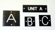
Unit Identification Examples |
Businesses that can supply phenolic labels may be listed in your phone book yellow pages under the classifications “Engraving”, “Trophies” or “Plaques” or located by performing an internet search. |
Multi-unit meter base installations, and other areas such as commercial buildings with meters and equipment installed on building walls in an alley or on the back walls of a strip mall, where there may be confusion of which premise is served by which meter must be permanently identified with phenolic labeling in compliance with the following requirements, the account will remain in the owner's name until the units have been verified by the appropriated District personnel.
Material and Format of Labels
- Engraved phenolic labels shall be used.
- Labels shall have plain block letters or numbers with a contrasting background.
- Block letters shall be at least 1/2" (12.70mm) minimum in height unless specifically required to be larger by the District.
Information on Labels
- Labels shall clearly indicate corresponding unit served by each meter.
Placement of Labels
- Labels will not be placed such that they obscure any information printed or labeled on the equipment.
- Position the label so that it is readily visible and that it is obvious what equipment the label describes.
Attachment of Labels
- Labels shall be smoothly attached to the metering equipment with no overlaps, protrusions or sharp edges and corners.
- Labels shall be applied in a craftperson-like manner and never applied over existing phenolic labels.
- Labels may have self-adhesive backs to aid in installation but each label shall have at least 2 holes (larger labels shall have at least 4) and be secured to the piece of equipment with appropriate sized pop-rivets or screws to keep the label from being unintentionally removed. All labels shall be installed and secured with pop-rivets or screws before they will be accepted by the District. Use caution when drilling and installing pop rivets or screws to avoid accidental contact with conductors.
G. Clearances
- All meter enclosures shall be readily accessible, i.e., not plastered in or built in. If installed in a recessed opening, the socket shall be arranged so that the minimum vertical distance between socket centers is 10 inches and the minimum horizontal distance is 8 inches. Refer also to Figure 5-9 for recessed meter clearances.
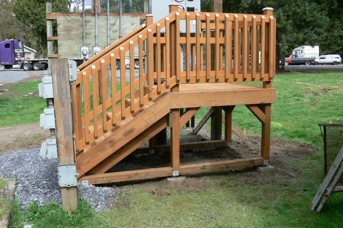
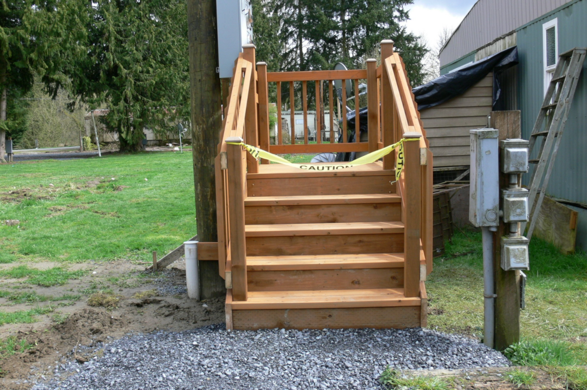
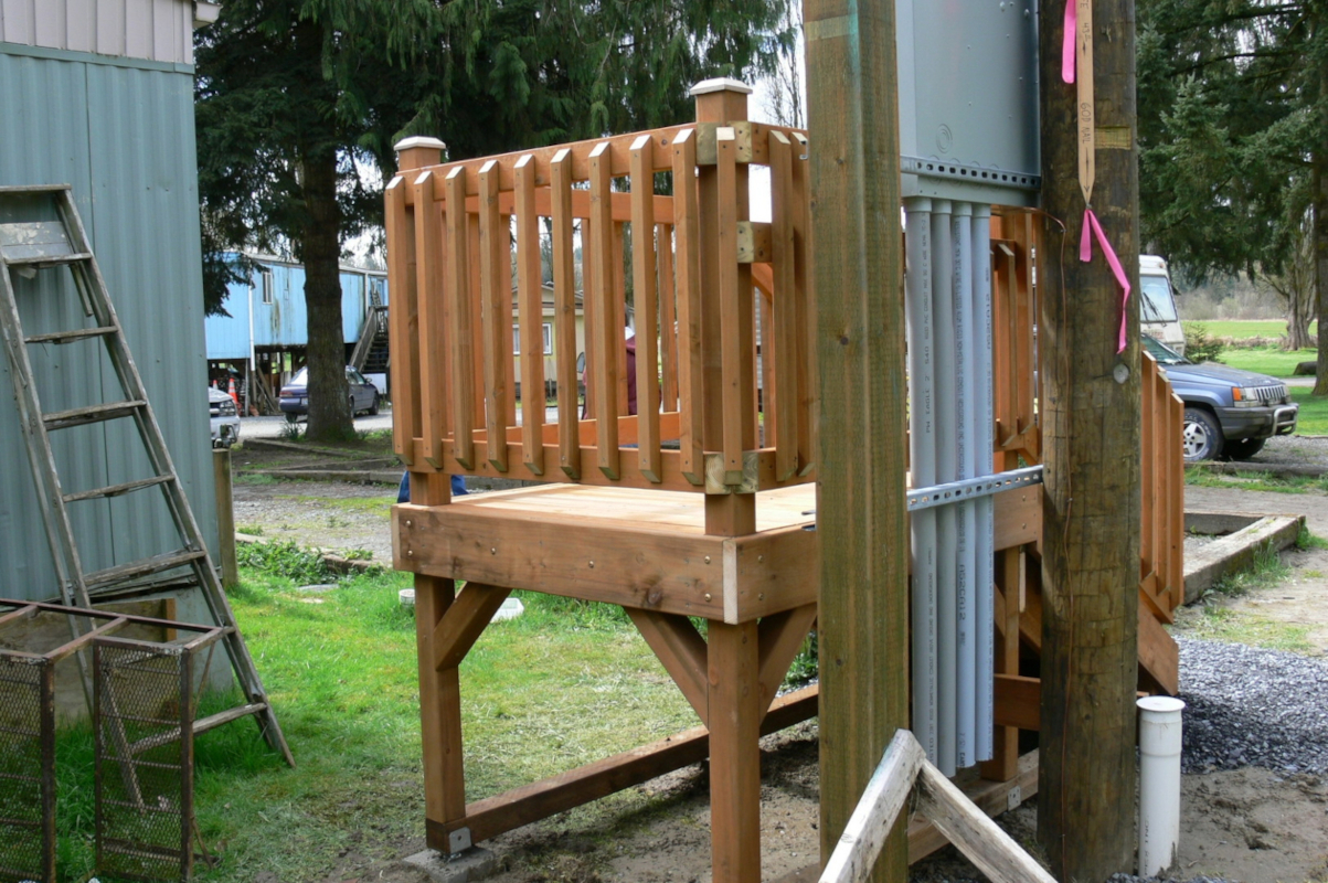
- Working space in front of meters or metering equipment shall not be less than 36 inches, measured from the front of meter glass. The height clearance of this area shall not be less than 7 feet above the finished grade, floor or working platform. The platform must be safely accessible via a permanent stairway. The platform, railing and stairway shall conform to all local building codes and regulations. The platform must be submitted and approved prior to and after actual construction by using the District's Variance Request form in Section 2. Refer to Figure 5-12 through Figure 5-14 for an example of an approved platform.
-
Electric meters shall be installed a minimum of three (3) feet from Natural Gas Meters, measurement shall be from edge to edge. In accordance with the requirements from:
National Electrical Safety Code, (NESC) IEEE C2-1997.
National Electrical Code (NEC) NFPA 70-1996
Flammable and Combustible Liquids Code, NFPA 30-1996
Standard for the Production, Storage and Handling of Liquefied Natural
Gas, NFPA 59A-1994.
- Working spaces in back of a freestanding switchboard shall not be less than 36 inches from the panel to the rear wall with provisions for safe exit.
H. Equipment Height
-
The meter height shall not be more than 6 feet nor less than 4 feet above the finished grade or floor below the meter with the reference point being the center of the meter.
Exception A:
When multiple meters (seven or more) are located inside buildings in an approved meter room, the meter socket center shall not be higher than 7 feet and not lower than 3 feet above finished grade or floor immediately below the socket.
Exception B:
Pedestal meter height shall not be less than 3 feet or greater than 6 feet from finished grade with the reference point being the center of the meter. - The maximum height to the top of a current transformer enclosure is 8 feet. The minimum height to the bottom of the enclosure is 6 inches above final grade.
I. Meter Platform Landing Example (Figure 5-12)
J. Meter Sockets
- All single phase commercial services rated 60, 100 or 200 amperes with phase to phase voltage of 300 volts or greater shall be safety socket type. Phase to phase voltage under 300 volts shall be safety socket type or have link-type manual by-pass.
- Ring type meter sockets only.
- Slide-link and lever-type by-passes are not allowed.
- Meter bases with automatic circuit closing devices are prohibited.
-
Arrangement of Meter Sockets
- Sockets and socket enclosures shall be designed in accordance with the latest revisions of ANSI C.12.7 standards for watt-hour meter sockets, EEI Publication MSJ-7 and with Underwriters Laboratories Standard For Meter Socket UL 414.
- Socket forms or arrangements to provide correct metering for the various systems used in the District are illustrated in Figure 5-12 through Figure 5-14.
- Meter bases shall be mounted plumb and be securely fastened to the structure to withstand forces of the installation or removal of the meter.
- Unused threaded openings and knockouts in trough type enclosures must be fitted with approved plug locked in place from the inside.
- Meter bases with automatic circuit closing devices are prohibited.
- Taps are not allowed in meter sockets or enclosures.
- Meter socket enclosures are not to be used as a raceway.
- The line supply conductors to a socket shall be connected to the top terminals and the load supply conductors shall be connected to the bottom terminals.
-
Meter Sockets for Residential Underground Service:
- Services shall use listed or approved sockets that are 200 or 400 ampere rated.
- Minimum socket dimensions shall be 4 inches in depth, 10-1/2 inches in width and 14 inches in height. Exceptions to this ruling shall be made only by submitting a Variance Form for approval before wiring has begun.
- Conduit shall not enter the center of the bottom of the meter base, but shall be off to one side to provide conductor clearance.
- A three-wire 120/208 or a 277/480 volt service rated 200 amps or less requires a five terminal socket. The fifth terminal shall be in the nine o’clock position. A #10 insulated white wire from the neutral grounded conductor shall be connected to the fifth terminal. Refer to Figure 5-13 for terminal arrangements.
- Three phase four-wire services require a seven terminal safety socket. The neutral tap must be connected to the terminal second from the right on the bottom or load side. Refer to Figure 5-13 for terminal arrangements.
- When aluminum conductors are used, the meter socket must be listed or approved and clearly marked by the manufacturer that it is acceptable for aluminum conductor.
-
The neutral service conductor shall be bonded to the meter base using the grounding screw or bonding terminal. The neutral service conductor may be continuous from the weatherhead through the meter socket to the service panel or disconnect provided a neutral tap for metering is not required. All neutral taps must be in the meter enclosure.
-
Potential taps, including the neutral tap, shall be located behind a sealed panel.
- A meter socket with test switch provisions shall be installed by the customer on all metering using current transformers. Refer to Figure 5-16 for minimum socket dimensions for single phase, three phase and Network Metering.
-
Feed-Through Bus
-
On overhead services when a feed through bus style meter socket which has lower bus energized at all times, the following procedures will be accomplished by the customer or his contractor prior to acceptance by the District. Refer to Figure 5-17.
- The lower line bus shall be insulated.
- The lower line bus shall be labeled as " Energized".
- The lower line bus shall be tagged as "HOT".
- The unit will then be energized and a barrel bolt lock on the lower left-hand panel will be installed by the District.
-
Known units of this type are:
Cutler Hammer Cat. No. CMBE88B200BTS and Cat. No. BR MBE48B200BTS.
-
On overhead services when a feed through bus style meter socket which has lower bus energized at all times, the following procedures will be accomplished by the customer or his contractor prior to acceptance by the District. Refer to Figure 5-17.
| Self-Contained | Voltage | Instrument Transformer Metered | |||
| No. of Terminals | Socket | No. of CT's | No. of Terminals | Socket | |
| Single Phase | Single Phase | ||||
| 4 | A | 120/240 | 2 | 6 | C (w/ Test Switch Provisions) |
| 4 | A* | 120/240 | |||
| 4 | A | 240/480 | 2 | 6 | C (w/ Test Switch Provisions) |
| Three Phase 3 Wire Network | Three Phase 3 Wire Network | ||||
| 5 | B** | 120/208 | 2 | 8 | F (w/ Test Switch Provisions) |
| 5 | B** | 277/480 | 2 | 8 | F (w/ Test Switch Provisions) |
| Three Phase 4 Wire | Three Phase 4 Wire | ||||
| 7 | D | 120/208 | 3 | 13 | E (w/ Test Switch Provisions) |
| 7 | D | 120/240 | 3 | 13 | E (w/ Test Switch Provisions) |
| 7 | D | 240/480 | 3 | 13 | E (w/ Test Switch Provisions) |
| 7 | D | 277/480 | 3 | 13 | E (w/ Test Switch Provisions) |
Figure 5-13: Meter Sockets

* 320 Amp Meter Socket with Link Bypass
*Fifth meter terminal shall be installed in the 9 o'clock position
Three phase services metered with current transformers, the customer shall provide a meter socket with test switch provisions. These meter bases shall be a minimum of 20" x 10" x 4". Refer to figure 5-14


K. Multiple Meter Socket Self-Contained Arrangements
- Single phase service
- Four terminal meter sockets rated 200 amps or less.
- Multiple meter sockets from two to six are allowed without requiring a main disconnect. Refer to Figure 5-18.
- Solid bus bar type is required.
- Meter sockets can be arranged horizontally, vertically or combinations there of.
- Permanent service identification is required. Refer to Section 2-F and Section 5-F.
-
Three phase service under 300 volts, phase to phase, 200 amps or less.
- All load to be balanced between phases, ± 10%.
- Load center may be top or bottom connected.
- Load center to be approved by the District before being installed.
- Automatic bypass type meter sockets are not allowed.
- Slide link and Lever By-Pass are not allowed.
- Safety sockets are required.
- Permanent service identification for all meters is required. Refer to Section 2-F and Section 5-F.

L. Multiple Meter Socket with Disconnect-4 Wire Y Service

M. Meter Retaining Rings
- The District will furnish and install a meter ring for all District meter installations in compliance with District requirements.
-
Ringless, sealable, front panel type meter sockets are acceptable for maximum 200 ampere single phase residential services.
Exception:- Recessed meter sockets shall be ring type only.
- Multiple or gang metering, all sockets shall be ring type to accept lock rings.
- Individual Safety Sockets shall be ring type only.
N. Metering - Services Over 200 Amperes
- The preferred installation for single phase services rated 201 to 400 amps at 120/240 volts is a 400 amp meter socket for use with a class 320 meter. Refer to Figure 5-20.
- Ring type meter mounting only.
- Link type manual bypass is required.
- Slide link and lever type bypasses are not acceptable.
-
Single phase services 201 to 400 amps may use current transformer installations.
The customer shall furnish and install the current transformer enclosure. Refer to item 5 of this section for requirements. -
Single phase services 401 to 800 amps and three phase 201 to 800 amps may use a current transformer enclosure or a switchboard.
- When current transformer enclosures are used, they shall be installed on the outside of the building and shall comply with the requirements listed in item 5 of this section.
- The District will furnish, install and wire the current transformers in the current transformer enclosure.
- All services 801 amps and above shall be installed in switchboards. Refer to Section 5-O.
-
Current Transformer Enclosure Requirements
Note: There will be no new installations of current transformers mounted directly on service entrance masts, building walls or meter poles.- A "Current Transformer Enclosure" (commonly known as a "C T Can") is a separate enclosure which contains a commercially manufactured mounting base or landing pad to terminate the incoming and outgoing conductors and for mounting the current transformers.
- The customer shall furnish and install the current transformer enclosure and related equipment excluding the current transformers and meter wiring.
- The enclosure shall be UL approved. Enclosures shall be rain-tite type and sealable. Sealing provision shall be an integral part of the cover for installation of District seals.
- The typical cover of a current transformer enclosure shall be a single cover or the cover shall be hinged. Two-piece overlapping covers may be allowed on some larger CT enclosures (e.g. 36" wide by 42" high) check with the District's engineer before installing. The cover shall not be used for mounting meter(s) or other equipment.
- For single phase units the cabinet shall be 24" x 36" x 11" minimum, for three phase units the cabinet shall be 36" x 36" x 11" minimum. Refer to the NEC for additional requirements.
- Mounting bases or landing pads required for terminating conductors and mounting current transformers shall be as specified in drawing 328A single phase, or drawing 329A three phase of the EUSERC Manual. Refer to Figure 5-21.
- Enclosures shall be grounded.
- The mounting height of transformer enclosures shall be limited such that the top of the enclosure shall not be more than 8 feet above the floor or working platform of same unless exception is specifically permitted by the District. The minimum height shall be 6 inches above the floor or working platform level. Enclosures shall not be mounted in or under floor crawl spaces.
- Current transformer enclosures shall be mounted on the outside walls of buildings.
- All service entrance line side conductors shall be on the outside of the building.
- The meter socket shall not be separated from the enclosure by a distance greater than fifty feet.
- Current transformer enclosures shall contain only service conductors and transformers. The enclosure shall not be used as a junction box, or raceway for other wires or conduits.
- Current transformers are furnished, installed and wired by the District when approved current transformer enclosures are utilized for metering.
- Current transformer enclosures shall not be installed on ceilings. If the enclosure is installed on a balcony or platform, it must be available by a permanent stairway which conforms to OSHA standards.
-
Current Transformer Conduit
- The customer shall provide proper size conduit for the metering conductors between the meter socket and the current transformers. Flexible conduit, condulets and LB’s shall not be used.
- Current transformer enclosures must be connected to the meter socket or meter enclosure with conduit and shall be bonded by approved methods. A minimum of 1 inch rigid steel, EMT or Sch 80 PVC conduit is required.


O. Metering on Switchboard or Panels
- Multiple Self-Contained Metering
- The clearance space around each meter socket shall not be less than 1 inch at the top and sides nor less than 2 inches at the bottom.
- Individual disconnects shall be on the load side of each meter socket.
- All unmetered compartments, on the line side of the meter, shall be sealable with padlock-type seals.
-
Current Transformer Switchboard Metering
- All services 801 amps and above shall be installed in switchboards.
- All services installed in switchboards shall be metered with large window current transformers. See EUSERC Drawings 330 and 322 for details. Bus link kits are required if the switchboard is built to EUSERC drawing 319 or 320
- Prior to the manufacture of the switchboard, the customer shall submit the switchgear drawing by means of a paper copy or electronic format to the District for approval and determination of the type meter or meters that will be used, type and size of current transformers and arrangements for mounting. Switchboards shall conform to EUSERC Standards approved by the District as listed on the EUSERC acceptability pages.
- Provision for current transformers shall be built into the bus of the switchboard (this shall be a sealable compartment, accessible only to the District).
- The District will furnish current transformers after approval of submitted drawings. The contractor shall pick up current transformers at the District's Meter Department (1802 75th St. SW, Everett).
- Working space requirements for meter socket and associated equipment shall be in compliance with Section 5-G.
- The electrical contractor shall install the metering socket and metering wires from the current transformer compartment to the meter socket. Current transformer instrument conductors shall be sized and color coded as indicated in Table 2 of this section.
- All unmetered compartments shall be sealable with padlock–type seals.
-
The meter socket itself shall be on the outside of the building. Meters shall not be mounted on panels covering compartments which contain current transformers, fuses, switches, or any other devices that will require servicing, changing or adjusting, necessitating the breaking of seals on meter panels.
Exception:
The meter and test switch may be mounted on the front of the Current Transformer compartment when, and only when, the switchgear is in a qualifying meter room (7 or more active meters). - The District's Meter Department personnel will connect the metering wires at the current transformers enclosure and the meter socket.
| * Distance and Conduit Size | Voltage Wires | Current Wires | Voltage Wires | Current Wires |
| 50 ft or Less 1" Conduit Minimum | Single Phase | Three Phase | ||
| 1 #12 Red | 1 #10 Black | 1 #12 Red | 1 #10 Black | |
| 1 #12 Orange | 1 #10 Brown | 1 #12 Orange | 1 #10 Brown | |
| 1 #10 White | 1 #12 Yellow | 1 #10 Blue | ||
| 1 #10 Green | 1 #10 White | |||
| 1 #10 Green | ||||
|
||||
Notes:
- THW or better insulation is required. TW wire is not acceptable.
- Tape color coding of wire is not allowed.
- The District must be contacted for special instructions if the distance between the current transformer compartment and the meter socket exceeds 50 feet.
- The customer shall provide proper size conduit and copper secondary metering conductors between the meter socket and the current transformers. Flexible conduit, condulets and LB's shall not be used.
- A minimum of 1 inch rigid steel, EMT or Sch 80 PVC conduit is required. All metal enclosures must be grounded per NEC.
- At all current transformer metering sockets, the length of the metering conductors shall be one and a half times the length of the longest side of the meter socket enclosure.
Figure 5-20: Switchboard Current Transformer Metering

Note: Prior to the manufacture of the switchgear submit drawings to the District (Refer to 5.0.2.c.)
P. Secondary Metering Behind a Customer-Owned Transformer
-
Availability
A customer-owned transformer is allowed on the source side of a District's revenue metering point if the following conditions are met:- The services fed from the customer-owned transformer are exclusively residential.
- The building is considered a high rise according to the 2003 edition of the International Building Code (IBC), section 403.1.
- All applicable requirements in the District's Electrical Service Requirements Manual are met.
-
Metering of Losses
The losses in the customer's transformer shall be metered at two metering points: one on the primary side and one on the secondary side of the customer's transformer. The difference between the two readings are the losses in the customer's transformer.
All aspects pertaining to metering the losses shall conform to the requirements in Section 5, Meters and Service Entrance Equipment, of the District's Electrical Service Requirements Manual (ESR). -
Installation Costs
The customer shall pay all costs associated with the installation of additional metering equipment to determine the losses. -
Billing
The meter readings taken at the two metering points shall be entered into the District's billing system and the difference billed to the building owner's house meter account. -
Metering Transformer Energy
Subtractive metering is linked to the building owner's house meter account and if any of the transformer energy metering or house metering is disconnected all tenant metering will also be disconnected.
Transformers and subtractive meter bases must be permanently labeled Transformer O1-Line, Transformer O1-Load; Transformer O2-Line, Transformer O2-Load; Transformer O3-Line, Transformer O3-Load, in accordance with ESR Section 5-F. -
Building Electrical Facilities Agreement
The customer shall complete and sign the Building Electrical Facilities Agreement (refer to Section 5-Q.) whereby the customer acknowledges responsibility for all aspects of all equipment installed past the District's Point of Delivery (except for the metering equipment installed by the District) and consents to accept billing for the transformer losses on a single house account. This fully executed agreement will be filed and retained by the District's Executive Account Team. -
One-Line Diagram
The customer shall supply the District a one-line diagram of the proposed electric system between the District's Point of Delivery and every metering point. The customer shall not proceed with installation of the proposed metering until they receive a signed letter of acceptance from the District's Meter Department. -
Transformer Efficiency
The customer-owned transformers shall conform to the minimum efficiency ratings given in NEMA TP1-2002, Table 4-2. -
Customer Responsibility:
The customer is responsible for complying with the one-line diagram and transformer efficiency requirements. -
Sources
International Building Code, Section 403.1
NEMA TP1-2002, Table 4-2.
Q. Building Electrical Facilities Agreement
Building Electrical Facilities Agreement
R. Meter Rooms in High-Rise Buildings
Meter room locations in high-rise buildings shall be coordinated with the PUD Engineering and Meter Departments during the design stage of construction and must be approved prior to finalizing building design and start of construction.
Multiple meter rooms may be allowed in high-rise buildings if the following conditions are met:
- The building is considered a high rise according to the 2003 edition of the International Building Code (IBC), section 403.1.
- Each meter room conforms with the requirements in Section 5, Meters and Service Entrance Equipment of the District's ESR.
- All applicable requirements in the District's Electrical Service Requirements Manual are met.
Additional Requirements:
- The first meter room must be located on the ground level floor, after that one meter room will be allowed every third floor, maximum one meter room per floor.
- If there are multiple meter rooms in a building each meter room must have signage inside the room indicating how many meter rooms are in the building and showing the locations of each room.
- Each meter room shall have a BEST "SP" knobset, signage and meter base identification installed as per the requirements of this section.
- If exterior access into the building and interior access to each meter room location will be open and unrestricted during normal District working hours, no exterior or interior BEST "SP" knobsets are required other than on the meter room door. If exterior or other interior doors accessing interior meter rooms will be locked or otherwise restricted during normal District working hours, then a BEST "SP" knobset must be installed as per the requirements of this section on each door leading to each meter room.
- Should building access be by roll-up type door, electronic opener with exterior mounted keyway with "SP" insert shall be installed at each location.