872657.1 Fiberglass Tangent Crossarms
Click here for a PDF of this Material Standard
Revision 13
Apr 07, 2025
1. Scope
This specification applies to pultruded fiberglass tangent crossarms for mounting on round or flat electrical power poles and supporting energized electrical distribution conductors.
2. Reference Standards
Unless otherwise stated in this specification, the conductors shall comply with the latest revisions of the following standards:
ASTM A36 Standard Specification for Carbon Structural Steel
ASTM A123 Standard Specification for Zinc (Hot-Dip Galvanized) Coatings on Iron and Steel Products
ASTM A153 Standard Specification for Zinc Coating (Hot-Dip) on Iron and Steel Hardware
ASTM A220 Standard Specification for Pearlitic Malleable Iron
ASTM D578 Standard Specification for Glass Fiber Strands
ASTM D4364 Standard Practice for Performing Outdoor Accelerated Weathering Tests of Plastics Using Concentrated Sunlight
ASTM D7745Standard Practice for Testing Pultruded Composites
ASTM D8019 Standard Test Methods for Determining the Full Section Flexural Modulus and Bending
Strength of Fiber Reinforced Polymer Crossarms Assembled with Center Mount Brackets
ASTM F2329 Standard Specification for Zinc Coating, Hot-Dip, Requirements for Application to Carbon
and Alloy Steel Bolts, Screws, Washers, Nuts, and Special Threaded Fasteners
ASTM G90 Standard Practice for Performing Accelerated Outdoor Weathering of Nonmetallic Materials Using Concentrated Natural Sunlight
ASTM G154 Standard Practice for Operating Fluorescent Ultraviolet (UV) Lamp Apparatus for Exposure
of Nonmetallic Materials
3. Physical Characteristics
Tangent fiberglass crossarms and mounting brackets shall be drilled and dimensioned per the following drawings:
Figure 1: 7' 2-Pin Fiberglass Crossarm - Material ID 5003130
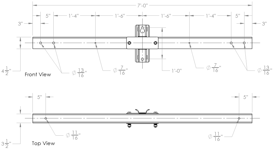
Figure 2: 10' 4-Pin Fiberglass Crossarm - Material ID 872657
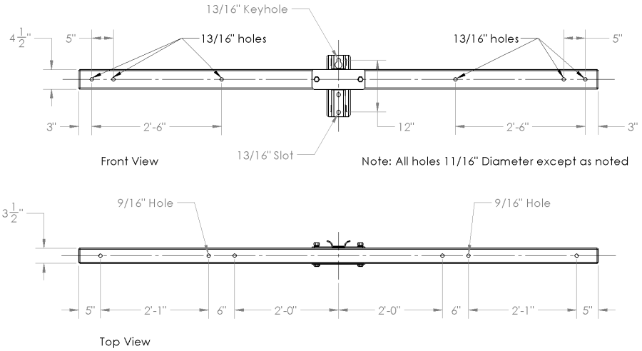
Figure 3: 13' 6-Pin Fiberglass Crossarm - Material ID 872665
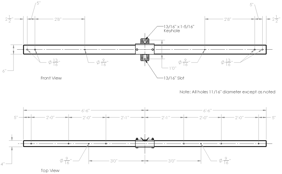
Figure 4: 15' 6-Pin Fiberglass Crossarm - Material ID 1002155
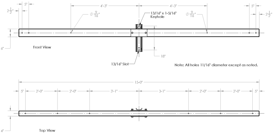
Figure 5: 18' Fiberglass Crossarm - Material ID 1001414
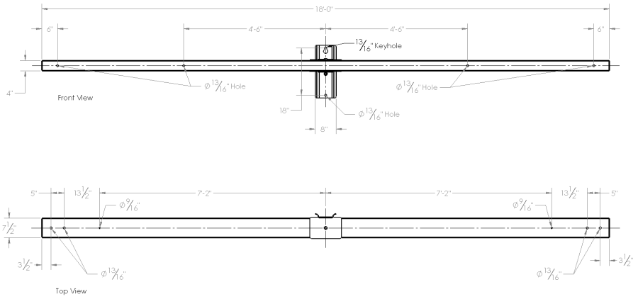
Figure 6: 26' Fiberglass H-Frame Crossarm - Material ID 1000960
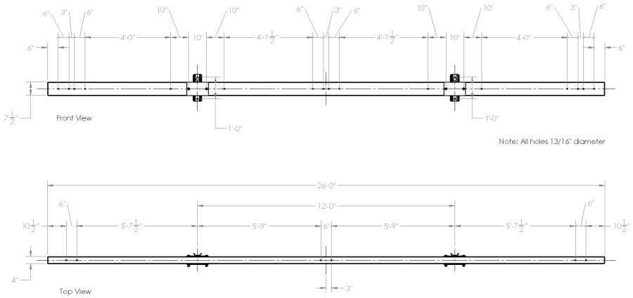
Figure 7: 30'x7.5"x4.0" Fiberglass H-Frame Crossarm - Material ID 873605
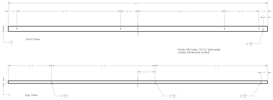
Figure 8: 36'x7.5"x4.0" Fiberglass H-Frame Crossarm - Material ID 873613
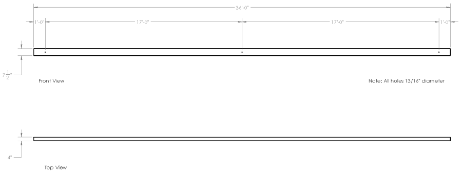
Figure 9: 10'x4"x6" Fiberglass Alley Crossarm - Material ID 1003556
Figure 10: 12'x4"x6" Fiberglass Alley Crossarm - Material ID 1003557
4. Construction
4.1 Weather and UV Protection
UV inhibitors shall be added to the polyester resin mixture and the outside surface of the crossarm shall be covered with a polyester surface veil to prevent fiber blooming. Also, the crossarm shall be coated with a minimum two full coats of polyurethane paint. Crossarms shall be tested in accordance with ASTM D4364 and G154, Cycle 1 for a minimum accelerated equivalent of 10,000hrs of UV exposure with no evidence of fiber blooming or other degridation to the structure.
4.2 Color
Color of the finished product shall be munsel gray.
4.3 Foam Filling
Crossarms shall be foam filled to minimize water ingress. Filler shall be either closed cell high density urethane foam or closed cell high density styrene foam.
4.4 Mounting Bracket
Crossarm mounting brackets shall be manufactured from high strength heat treated aluminum alloy, hot dip galvanized structural steel plate or hot dip galvanized ductile iron. All bolts, nuts and other hardware shall be hot dip galvanized. Mounting brackets shall be designed for installation on wood, steel, concrete or fiberglass poles with round or flat mounting surfaces.
4.5 End Caps
Crossarm ends shall be sealed with non-removable flush mounted inserts. External end caps are not acceptable.
5. Mechanical Characteristics
5.1 Ultimate Strength
Minimum ultimate strengths for 10, 13, 15, 18, 26, 30 & 36 foot crossarms are listed in Table 1, subject to the loading diagram below:
| Table 1 | |||||
|---|---|---|---|---|---|
| Crossarm | Working Load (lbs) |
Ultimate Load (lbs) |
Deflection (in/1000 lb) |
L (in) | a (in) |
| 7 foot | 2,500 | 5000 | 0.86 | 74 | 27 |
| 10 foot | 2,500 | 5,000 | 0.86 | 110 | 50 |
| 13 foot | 4,500 | 9,000 | 1.25 | 146 | 68 |
| 15 foot | 3,550 | 7,100 | 2.00 | 170 | 80 |
| 18 foot | 1,350 | 2,700 | 4.11 | 206 | 97 |
| 26 foot | 900 | 1,800 | 9.00 | 302 | 146 |
| 30 foot | 775 | 1,550 | 12.00 | 350 | 170 |
| 36 foot | 650 | 1,300 | 43.00 | 422 | 206 |
5.2 Maximum Allowable Deflection
Maximum allowable deflections for crossarms subject to long-term static loads shall not exceed the values listed in Table 1 above.
5.3 Compressive Strength
Compressive strength (S) in both the vertical and horizontal directions for any cross section (including foam filler) perpendicular to the crossarm longitudinal axes shall be a minimum of 1,500 psi without permanent deformation or damage to the fiber/resin matrix.
6. Electrical Characteristics
Fiberglass crossarms shall have an average dry 60 Hz BIL of no less than 15kV/inch and an average wet 60 Hz BIL of no less than 12kV/inch.
7. Identification
Each fiberglass crossarm shall be permanently marked with the manufacturer’s name or logo and date of manufacture.
8. Packaging
Fiberglass crossarms shall be shipped fully assembled with mounting brackets.
9. Warranty
Crossarms and their components shall carry a non-prorated warranty of 10 years from the date of delivery. Replacement units shall be new and come with a 10 year warranty from the date of delivery.