VAULTMAT1 Master Standard for Precast Vaults, Box Pads, Covers, and Accessories
Click here for a PDF of this Material Standard
Revision 2
Mar 17, 2020
1. Scope
This material standard applies to the general requirements for manufacturing and supplying precast concrete vaults, box pads, vault covers and accessories.
3. Reference Standards
All characteristics, definitions, terminology and tests, except as otherwise specified herein, shall be in accordance with
the following industry standards. When the following standards are superseded by an approved revision, the revision
shall apply.
Industry Standards:
| AASHTO HB-17 | Standard Specification for Highway Bridges, 17th Edition |
| AASHTO M-306 | Standard Specification for Drainage, Sewer, Utility, and Related Castings |
| ASTM A36/A36M-08 | Standard Specification for Carbon Structural Steel |
| ASTM A123/A123M-09 | Standards Specification for Zinc (Hot-Dip Galvanized) Coatings on Iron and Steel Products |
| ASTM A615/A615M-09b | Standard Specification for Deformed and Plain Carbon-Steel Bars for Concrete Reinforcement |
| ASTM C33/C33M-08 | Standard Specification for Concrete Aggregates |
| ASTM C150/C150M-09 | Standard Specification for Portland Cement |
| AWS D1.1/D1.1M - 2006 | Structural Welding Code - Steel |
| FAA AC 150/5320-6E Appendix 3 | Design of Structures for Heavy Airplanes |
| FAA AC 150/5370-10E Item D-751 | Manholes, Catch Basisns, Inlets and Inspection Holes |
| MFMA | Metal Framing Standards Publication - 2004 |
| NESC C2-2007 | 323. Manholes, Handholes and Vaults |
4. VAULT Material
All vaults shall be manufactured of concrete and reinforcing bars meeting a minimum compressive strength of 7,000 psi after 28 days. The concrete shall meet the requirements of ASTM C150 and C33. Reinforcing bars shall be sized appropriately for the specific vault and meet the requirements of ASTM A615.
5. Lifting Inserts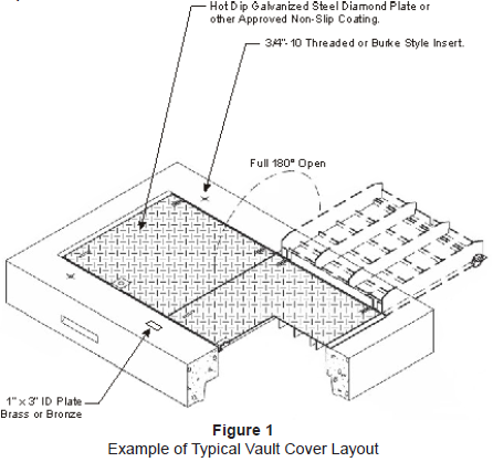
Vaults shall be equipped with lifting inserts, either threaded or Burke type, to enable a balanced picking procedure. See example, Figure 1.
5.1 Threaded Inserts
Threaded type lifting inserts shall be size 3/4"-10 manufactured of corrosion resistant stainless steel. All threaded inserts shall include removable threaded protective plastic caps installed flush with the vault surface.
5.2 Burke Inserts
Burke type lifting inserts shall be designed for use with Burke Ring Clutch lifters with a 2 ton rating. Burke inserts shall include removable plastic caps that securely fit onto the inserts and are installed flush with the vault surface.
6. Hatch Covers
When specified by the District, vault covers shall be equipped with hatch covers meeting the following requirements.
6.1 Hatch Construction
Hatch cover(s) shall be constructed from steel having a textured surface, either diamond plate, Slip-Not® Grade 3-coarse non-skid coating, Thermion SafTrax®, or Jensen MetalTech TraxPlate. Aluminum covers may also be acceptable with prior District approval. The frame for hatch cover(s) shall be securely anchored in the concrete cover (cast in place). Steel frame and hatch cover(s) shall be hot-dip galvanized in accordance with ASTM A123.
6.2 Hatch Opening
The cover(s) shall lay flat and provide a clear opening and be hinged such that a full 180° opening can be achieved. See example, Figure 1. Covers shall be equipped with a spring-assist assembly requiring no more than 55 lbs of force to operate. Covers shall have recessed lift handles.
6.3 Hatch Locking
Each cover shall be equipped with a spring-locking latch with a recessed 3/8" penta-head bolt. Optionally, the District may require provisions to padlock the vault cover in a recessed lock compartment.
6.4 Grounding
Provisions shall be made for the option of grounding the hatch cover(s) and frame(s) via a ground plate attached to the hinge side of the hatch cover frame. The plate shall include a 5/8" hole for mounting a District grounding connector.
6.5 Loading
Steel or aluminum hatch cover assemblies (hatch, frame and concrete cover) shall have a minimum rating of H-20 or HS-25 loading per AASHTO HB-17. Round cast iron manhole covers shall have a HS-25 minimum rating.
Airport/Port Authority rated covers shall meet or exceed FAA loading requirments and shall sustain a minimum proof load of 200,000 lb over a 9" x 9" contact area as detailed in AASHTO M-306.
7. Identification Plate
All District vault covers shall include a 1" wide x 3" long x 3/16" thick (min.) brass or bronze blank identification plate (vault tag). See example, Figure 1. Vault tags shall be centered in front of the hatch cover on the side where the latch is located and embedded so it is flush with the surface of the vault's cover. The top surface of the plate shall not be covered over with concrete.
8. Vault Lid Marking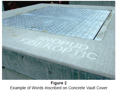
Unless otherwise specified by the District, covers of subsurface electrical vaults that do not have pad-mounted equipment mounted on them shall have the identifying word "ELECTRIC" or "POWER" neatly and permanently marked in plain uppercase letters. Letters shall be a minimum of 2” and a maximum of 3” in height and may be cast into the concrete cover or bead welded on the metal hatch cover. The identifying word shall be squarely in alignment with a vault edge for a neat appearance and shall be placed in a consistent location from one vault cover to the next.
Where practical, the identifying word shall be aligned so it can be read from the front of the vault, that is, from the side of the vault where the door latch and bronze vault number tag are located. See example, Figure 2.
9. Concrete Finish
The top surface of the vault shall have a brush finish.
All top edges shall be tooled.
10. Knockouts
When specified by the District, vaults shall include cable/conduit knockouts. Knockouts shall be designed in a manner such that removal can easily be accomplished with a sledgehammer. See example, Figure 3.
11. Cable Pulling Irons
- When specified by the District, vaults shall include pulling irons. See example, Figure 3.
- Irons shall be manufactured from hot-dipped galvanized steel.
- 1/2" or 7/8" diameter pulling irons shall be required, depending on vault size and application.
- 1/2" pulling irons shall be rated for a minimum tensile strength of 5,000 lb.
- 7/8" pulling irons shall be rated for a minimum tensile strength of 10,000 lb.
12. Interior Equipment Mounting Hardware
When specified, inner vault walls shall have embedded 1-5/8" x 1-5/8" stainless unistrut channel installed for mounting junctions or other equipment. See example, Figure 3.
13. Sump
A sump shall be present in the bottom of each vault. The size and placement of the sump shall be specified by the District. The bottom of the sump shall be designed such that it can be knocked out if necessary. See example, Figure 3.
14. Vault Sealing Material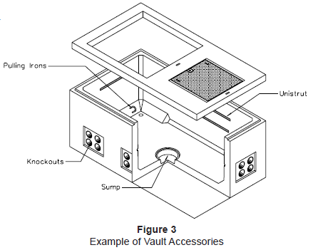
ConSeal CS-101 Butyl Sealant, District Cat. ID 1001896, shall be included with all 3-piece vaults.
Equivalent sealants may be used with District approval. An adequate amount of sealant shall be supplied to apply a ring to both the top and bottom mating surfaces.
Equivalent sealants shall be butyl based, permanently flexible, watertight, require no surface priming, and be in a double-sided tape form, similar to mastic.
15. Shipping
Each vault shall be shipped to the job site or storage location designated by the District.