765604.1 Miscellaneous Pads and Covers
Click here for a PDF of this Material Standard
Revision 1
Dec 13, 2024
1. Scope
This specification applies to precast concrete covers and pads specifically for electrical use.
2. Material ID Numbers
The following vault Cat ID's shall conform to the corresponding diagram dimensions:
2.1 Covers and Pads
| Material ID | Description | Section |
|---|---|---|
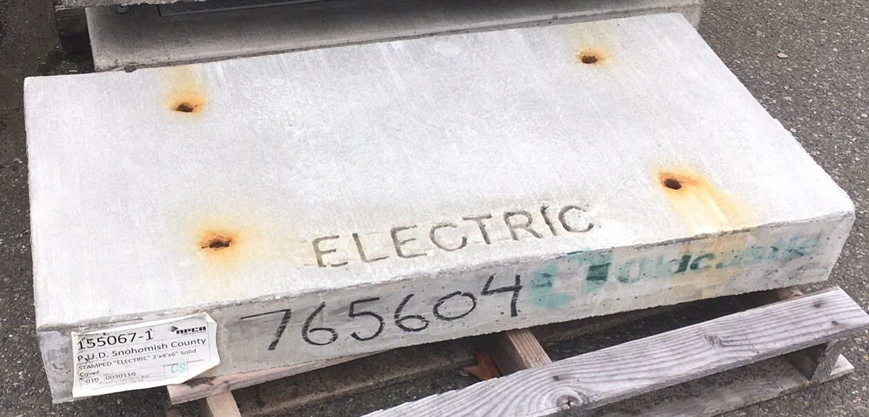
| 765604 | 2'0 x 4'0 x 0'6, solid | 9.8 |
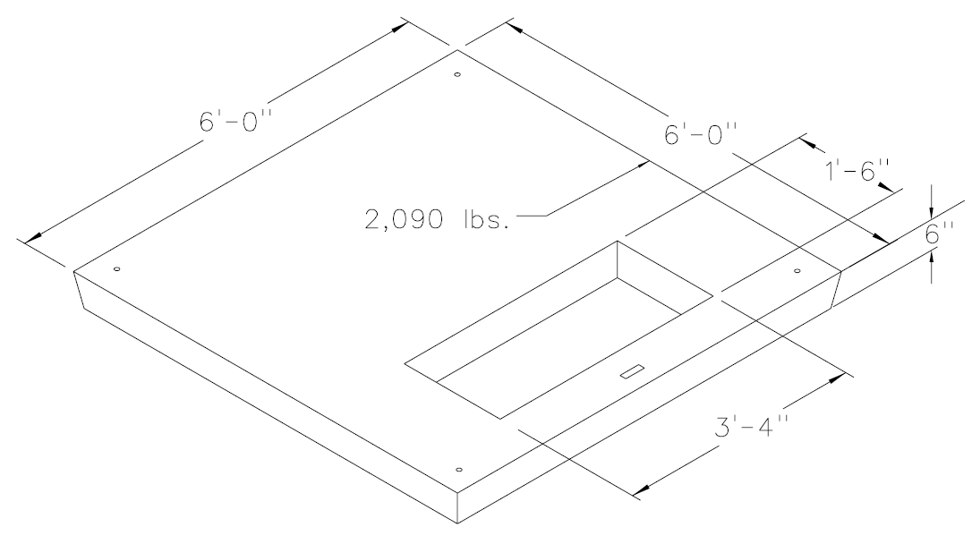
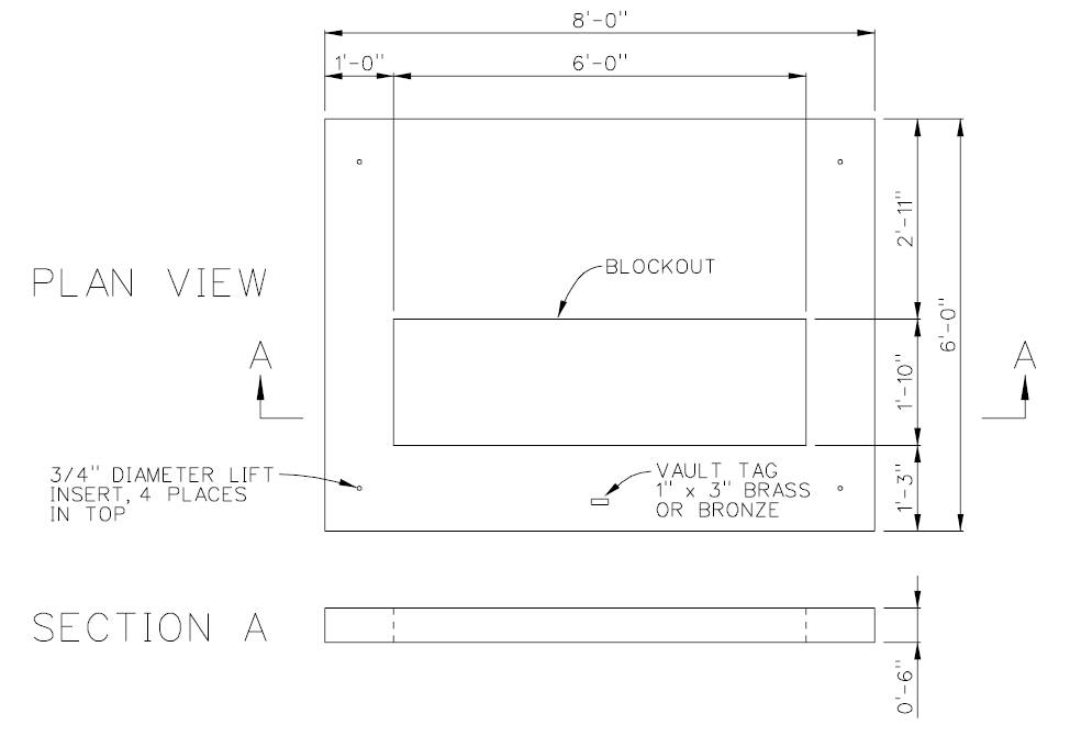
| 781444 | 6'0 x 6'0 x 0'6, with 18" x 40" opening for padmount transformers | 9.2 |
| 790023 | 5'4 x 6'0 x 0'4, solid for temporarily covering switch cabinet vault openings | 9.9 |
| 1000211 | 5'2 x 7'4 x 0'6, with 50" x 19" opening for primary metering cabinets | 9.5 |
| 1001561 | 5'4 x 6'8 x 0'6, with 54" x 62" opening centered on the cover | |
| 1001564 | 6'0 x 6'0 x 0'6, with 32" x 48" opening for Copper/Kyle Type RVAC three phase 15kV Vacuum Switch | 9.4 |
| 1001687 | 6'8 x 6'8 x 0'6, with 15" x 46" opening for padmount capacitor banks | 9.6 |
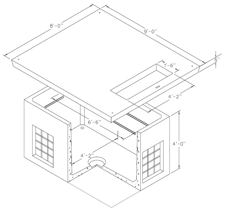
| 1001689 | 8'0 x 9'0 x 0'6, with 18" x 50" opening | 9.1 |
| 1001690 | 4'0 x 5'4 x 0'6, with 36" x 36" hatch | |
| 1001876 | 6'0 x 6'0 x 0'6, with 15" x 40" opening for three phase 200A j-box cabinets | 9.7 |
| 1002119 | 32" round, ductile iron H-20 rated manhole | |
| 1002153 | 6'0 x 8'0 x 0'6, with 22" X 72" opening for three phase 600A j-box cabinet | 9.3 |
| 1003752 | 4'0 x 5'4 x 0'6, with 36" x 36" hinged and locking H-20 rated galvanized steel cheveron grate lid, for replacing damaged submersible transformer vault covers requiring this size | |
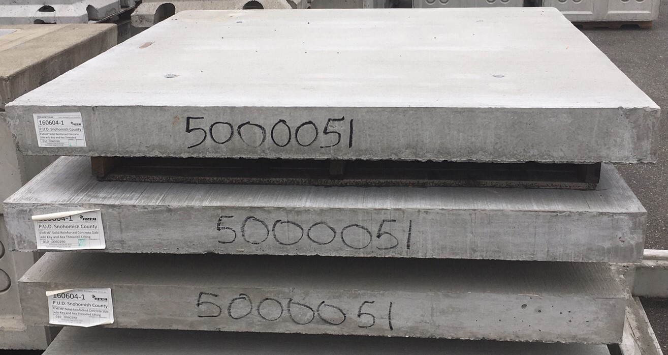
| 5000051 | 6'0 x 6'0 x 0'6, solid | 9.10 |
| 5006634 | 4'8 x 4'8 x 0'6 without keying with 12" x 28" opening for padmount transformers |
3. Referenced Standards
All material, accessories, and marking for District vaults, pads, and covers shall adhere to the specifications of District Material Standard VAULTMAT1.
4. Pulling Irons
Vaults shall be equipped with 5/8" pulling irons located in the lower corners, unless otherwise specified by the District.
5. Interior Equipment Mounting Hardware
All vaults shall be equipped with interior equipment mounting hardware.
6. Lifting Inserts
All covers shall be equipped with corrosion-resistant stainless steel threaded-type lifting inserts as appropriate for the structure's weight. Each threaded insert shall be equipped with a removable threaded plastic protective cap installed flush with the riser's top surface.
7. Identification
All vaults, covers, and pads shall be marked in compliance with VAULTMAT1.
8. Hatch Covers
All hatch covers shall be constructed of H-20 rated Diamond Plate unless otherwise specified by the District. In individual cases where this is not sufficient, the District shall have the option to specify a Port Authority rating and/or a SlipNot™ finish.
9. Dimensions
Vaults, pads, and covers shall have the following dimensions and knockout distribution (where applicable). Note that multiple covers may fit each vault and that covers may have the same dimensions with different accessories, i.e. Diamond Plate Hatch vs. Steel Plate w/ SlipNot™ Hatch.
9.1 4'8" x 7' x 4' Vault & 8' x 9' Cover w/ 50" W x 18" D Access Opening
9.2 6' x 6' x 6" w/ 18" D x 40" W Blockout, Padmount Transformer
9.3 8' x 6' x 6" w/ 72" x 22" Access Opening for 600A 15kV Padmounted J-Box Cabinet
9.4 4'8" x 4'8" x 3'6" & 6' x 6' x 6" Cover w/ 32" x 48" Access Hole

9.5 7'4" x 5'2" x 6" w/ 50" x 19" Blockout (for Primary Metering Cabinet)

9.6 6'8" x 6'8" x 6" w/ 15" x 46" Blockout (15kV Padmount Capacitor Bank)

9.7 6' x 6' x 6" w/ 40" x 15" Blockout, 3Ø 200A 15kV J-Box Cabinet

9.8 2'0 x 4'0 x 0'6, solid
9.9 5'4 x 6'0 x 0'4, solid for temporarily covering switch cabinet vault openings
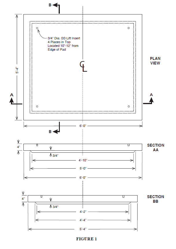
9.10 6'0 x 6'0 x 0'6, solid