786204.1 Aluminum Compression Terminal Lugs
Click here for a PDF of this Material Standard
Revision 7
Jan 9, 2011
1. Scope
This specification applies to Aluminum Compression Terminal Lugs used in terminating aluminum and copper conductors to aluminum and copper surfaces.
2. Reference Standards
All characteristics, definitions, terminology, voltage designations and tests, except as otherwise specified herein, shall be in accordance with the following industry standards for compression terminal lugs. When the following standards are superseded by an approved revision, the revision shall apply.
Industry Standards:
ANSI/NEMA C119.4 - 2011 American National Standard for Electric Connectors-Connectors for Use Between Aluminum-to-Aluminum and Aluminum-to-Copper Conductors Designed for Normal Operation at or Below 93°C and Copper-to-Copper Conductors Designed for Normal Operation at or Below 100°C
ANSI/NEMA CC 1 - 2011 Electrical Power Connection for Substations
3. Physical Characteristics
Terminal lugs shall have one or two hole NEMA standard pads and shall be manufactured from cast aluminum or formed aluminum tubing. Each lug shall be factory-filled with an oxide-inhibiting compound and capped to prevent contamination from foreign material. Tin plating is required on all lugs.
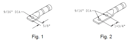
4. Size and Die Requirements
Refer to the table below for terminal lug conductor sizes, pad styles, length ranges and installation die requirements. Terminal lugs must fit concentric stranded and compressed stranded conductors as well as the indicated compact stranded conductors. Terminal lugs that cannot provide adequate mechanical and electrical connections using the dies indicated below will not be acceptable. Each terminal lug must be permanently marked with conductor size, Burndy die index, number of crimps, manufacturer's name or trademark and part number.
| Cat. ID | Conductor Size | Pad Style | Length | Burndy Die Index |
|---|---|---|---|---|
| 786204 | #1-#2 Str, #1 Cmpct | Fig. 1 | 3-¹⁄₄" ± ¹⁄₈" | 249, K-840 |
| 786353 | 1/0 Str. 1/0-2/0 Cmpct | Fig. 1 | 3-¹⁄₄" ± ¹⁄₈" | 249, K-840 |
| 786361 | 2/0 Str, 3/0 Cmpct | Fig. 1 | 3-¹⁄₄" ± ¹⁄₈" | 249, K-840 |
| 786379 | 3/0 Str, 4/0 Cmpct | Fig. 1 | 3-¹⁄₄" ± ¹⁄₈" | 249, K-840 |
| 786395 | 4/0 Str, 250-300 Cmpct | Fig. 1 | 3-¹⁄₄" ± ¹⁄₈" | 249, K-840 |
| 101569 | 4/0 Str, 250-300 Cmpct | Fig. 2 | 6" ± ¹⁄₂" | 249, K-840 |
| 786402 | 250 Str, 300 Cmpct | Fig. 2 | 6" ± ¹⁄₂" | 317 |
| 786410 | 350 Str, 400 Cmpct | Fig. 2 | 6" ± ¹⁄₂" | 299, 655 |
| 10016953 | 400 Str, 500 Cmpct | Fig. 2 | 6" ± ¹⁄₂" | 299, 655 |
| 786436 | 500 Str, 600 Cmpct | Fig. 2 | 6-¹⁄₂" ± ¹⁄₂" | 299, 655 |
| 786270 | 600 Str, 750 Cmpct | Fig. 2 | 7" ± ¹⁄₂" | 473, 786 |
| 786444 | 750 Str, 900 Cmpct | Fig. 2 | 7-³⁄₄" ± ³⁄₄" | 301 |
| 786452 | 1000 Str | Fig. 2 | 7-³⁄₄" ± ³⁄₄" | 301 |