785909.1 Set Screw Bar Connectors for Pad-Mounted Transformers
Click here for a PDF of this Material Standard
Revision 1
Jan 17, 2013
1. Scope
This Material Standard applies to set screw bar type aluminum secondary connectors for use in padmounted transformers.
2. Reference Standards
Except as modified herein, bar connectors shall meet the applicable requirements of the latest revisions of the following:
ANSI C119.4 American National Standard for Electrical Connectors
3. Construction
3.1 General
Aluminum set screw secondary bar connectors shall be preassembled with a removable adapter for mounting on a 5/8" - 11 UNC-2A threaded secondary terminal stud in a padmounted transformer.
3.2 Materials
The set screw connector bar and stud adapter shall be constructed of high-strength, high-conductivity aluminum alloy (6061-T6 or equivalent). If the set screws are constructed of a different alloy than the set screw body, both alloys shall have the same thermal expansion rate.
3.3 Dimensions
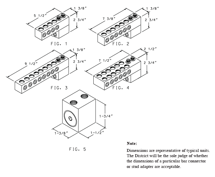
Set screw bar connectors and stud adapters shall have overall dimensions similar to those indicated for typical units in Figures 1 - 5 on page 2 of this document. The District will be the sole judge of whether the dimensions of a particular bar connector or stud adapter are acceptable. Connector bars, stud adapters and associated parts shall be free of cracks, burrs, sharp projections and other defects. All corners shall be rounded.
3.4 Number of Terminations
Set screw bar connectors are to be provided for the termination of 4, 6, 8 or 12 conductors as specified by the District. An additional port for the termination of a street light conductor may be provided, but is not required.
Conductor ports shall be configured as shown in Figures 1 - 4.
3.5 Conductor Ports
Conductor ports shall accept aluminum and copper conductors, #6 solid through 350 kcmil Class B concentric lay stranded. Oxide inhibiting compound shall not be provided in the conductor ports.
3.6 Set Screw
The set screw in each port shall be one-piece with rounded (cone-shaped) bottoms. Set screws shall be designed for operation with a 5/16" hex allen wrench. Set screws shall be oxidation resistant, clean and smooth operating. Conductor port set screws shall be right-hand operable with the stud adapter mounted on the bottom of the bar.
3.7 Stud Adapters
3.7.1 A stud adapter shall be installed on each bar connector for mounting on a 5/8" - 11 UNC-2A threaded secondary terminal stud in padmounted transformers. The adapter shall be mounted at one end of the connector bar on the side perpendicular to the set screw allen wrench wells as illustrated in Figures 1 - 4.
The bolts used to mount the adapter to the connector bar shall not broach the stud-mounting hole in the adapter.
3.7.2 Two 3/8" x 1-1/2" - 16 cap screws with stainless steel belleville spring or split spring lockwashers shall be used to secure the stud adapter to the connector bar. Cap screws shall be corrosion-resistant and may be either regular hex-head type or broached for a 5/16" hex allen wrench. The two mounting holes in the connector bar, through which the stud adapter cap screw mounting bolts pass, shall be 7/16" in diameter and shall be spaced 15/16" center-to-center.
3.7.3 Adapters for mounting on 1" - 14 UNC-2A threaded secondary terminal studs in 100 kVA and 167 kVA padmounted transformers shall be supplied separately. One-inch stud adapters shall be supplied without bolt assemblies for mounting the adapter to the connector bar unless otherwise specified.
3.7.4 Both 5/8" and 1" stud adapters shall be designed to be screwed onto the threaded secondary terminal studs in padmounted transformers. Slip-fit type stud adapters are not acceptable. The stud adapter shall be equipped with a through-hole type locking screw situated in-line with the transformer secondary terminal stud. A locking screw directed perpendicular to the stud is unacceptable. The locking screw shall be designed for operation with a 5/16" hex allen wrench. The stud mounting hole in the stud adapter shall be pre-loaded with oxide inhibiting compound on the threads and shall be capped.
3.8 Labelling
The name or insignia of the manufacturer and the conductor range accommodated by the connector shall be clearly stamped on the connector bar. Although not required, it is desirable to have the manufacturer's name or insignia stamped on the stud adapter too.
4. Electrical Requirements
As a minimum, the connector shall have passed the latest revision of ANSI C119.4, Class "A" connector electrical performance test or equivalent without having to retighten the set screws.
5. Material ID Numbers
This Material Standard applies to the following items:
| Cat. ID | Description | Figure |
|---|---|---|
| 785909 | 4-port secondary set screw bar connector with 5/8" stud adapter | 1 |
| 785917 | 6-port secondary set screw bar connector with 5/8" stud adapter | 2 |
| 785925 | 8-port secondary set screw bar connector with 5/8" stud adapter | 3 |
| 785933 | 12-port secondary set screw bar connector with 5/8" stud adapter | 4 |
| 503963 | 1" stud adapter | 5 |