785470.1 15kV 600A Deadbreak Elbow Terminators and Accessories
Click here for a PDF of this Material Standard
Revision 2
May 13, 2016
1. Scope
This specification applies to 15kV Class 600 amp deadbreak elbow terminators, components and accessories. Terminators, components and accessories shall be insulated, fully shielded, completely submersible and designed for hotstick operation on a de-energized 12.47 Grd. Y/7.2kV electrical distribution system.
2. Reference Standards
Except as modified herein, the terminators shall meet the applicable requirements of the latest revisions of ANSI/IEEE 386 and IEEE 592.
3. Ratings
| MINIMUM ELECTRICAL SPECIFICATIONS | |
|---|---|
| BIL (kV) | 95 |
| Min. Corona Level (kV) | 11 |
| AC withstand: | 34kV, 60Hz, 60 sec. |
| DC withstand: | 53kV, 15 min. |
| 600A Current Rating (Continuous) | 600A rms |
| 600A Current Rating (Momentary) | 10,000 A rms symmetrical for 12 cycles |
4. 600 Amp Elbow Housing
4.1 Stock Code Numbers
This specification applies to the following District stock code number: 785462
4.2 General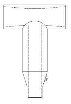
The 600 amp elbow housings shall be designed for connection to 8.3/15.2 kV 600 amp deadbreak interfaces manufactured in accordance with ANSI/IEEE 386. Elbow housings must be interchangeable with elbow housings supplied with elbow terminator kits as described in Section 8.
4.3 Construction
All rubber components, including the elbow body, conductive shield and conductive insert shall be molded of EPDM rubber.
4.4 Identification
The following information shall be molded into each elbow housing:
- Manufacturer's Name or Trademark
- Date of Manufacture
- 600 Amp Continuous Current Rating
- 15.2 kV Voltage Rating
- The word "DEADBREAK"
4.5 Packaging
Each elbow housing shall be individually packaged and shall include the elbow housing and installation instructions.
5. 600 Amp Cable Adapter
5.1 Stock Code Numbers
This specification applies to the following District stock code numbers:
| Cable Size | Cable Insulation Dia. (Nominal) |
Stock Code No. |
|---|---|---|
| 350 kcmil Al | 1.080" | 785496 |
| 750 kcmil Al | 1.400" | 785553 |
| 1000 kcmil Al | 1.545" | 785470 |
5.2 General
Cable adapters provide stress relief and an interference fit between the cable insulation and the 600 amp elbow housing described in Section 4.
5.3 Construction
All rubber components, including the conductive shield and stress relief shall be molded of EPDM rubber.
5.4 Identification
The following information shall be permanently marked into each cable adapter:
- Manufacturer's Name or Trademark
- Date of Manufacture
- Cable O.D. Range
- 15.2 kV Voltage Rating
5.5 Packaging
Each cable adapter shall be individually packaged and shall include the cable adapter and installation instructions.
6. Drain Wire Sheild Adapter
6.1 Stock Code Numbers
This specification applies to the following District stock code numbers:
| Cable Size | Cable OD (Nominal) | Stock Code No. |
|---|---|---|
| 350-1000 kcmil Al | 1.980" | 1000198 |
6.2 General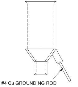
Drain wire shield adapters provide a grounding connection and an environmental seal over the drain wires on drain wire shielded cables. A water tight port for a #4 copper grounding rod shall be molded into the adapter body. One end of the ground rod shall be equipped with a crimp terminal for connecting the drain wires. The grounding end of the cable adapter shall provide an interference fit over the cable jacket while the other end shall povide an interference fit over the base of the 600 amp elbow housing described in Section 4.
6.3 Construction
All rubber components shall be molded of EPDM rubber. The grounding rod and crimp connector shall be tin plated copper
6.4 Identification
The following information shall be permanently marked into each shield adapter:
- Manufacturer's Name or Trademark
- Date of Manufacture
- Cable O.D. Range
6.5 Packaging
Each shield adapter shall be individually packaged and shall include the drain wire shield adapter and installation instructions.
7. 600 Amp Threaded Stud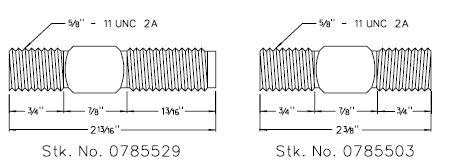
7.1 Stock Code Numbers
This specification applies to the following District stock code numbers: 785529 & 785503
7.2 General
Threaded studs are used to connect 600 amp elbow terminators to ANSI standard 8.4/15.2 kV 600 amp deadbreak interfaces.
7.3 Construction
Threaded studs shall be manufactured from high conductivity copper alloy. Studs shall be dimensioned and threaded as indicated in the adjacent drawing.
7.4 Packaging
Each threaded stud shall be individually packaged.
8. 600 Amp Elbow Compression Connectors
8.1 Stock Code Numbers
This specification applies to the following District stock code numbers:
| Cable Size | Conductor Dia. (Nominal) |
Stock Code No. (Fig 1) |
Stock Code No. (Fig 2) |
|---|---|---|---|
| 350 kcmil Al | 0.661" | 785561 | 785579 |
| 750 kcmil Al | 0.968" | 785545 | 785587 |
| 1000 kcmil Al | 1.117" | 785488 | 785595 |
8.2 General
600 amp elbow compression connectors provide a current carrying connection between the primary cable conductor and ANSI standard 8.3/15.2 kV 600 amp deadbreak interfaces. The compression connectors shall meet the applicable requirements of the latest revisions of ANSI C119.4 and NEMA CC1. Each connector shall be factory filled with an oxide inhibiting compound and capped to prevent contamination from foreign material. The connector shown in FIG. 1 shall be equipped with a 15/16" - 9 NC threaded top. The connector shown in FIG. 2 shall be equipped with an unthreaded 11/16" diameter hole.
8.3 Construction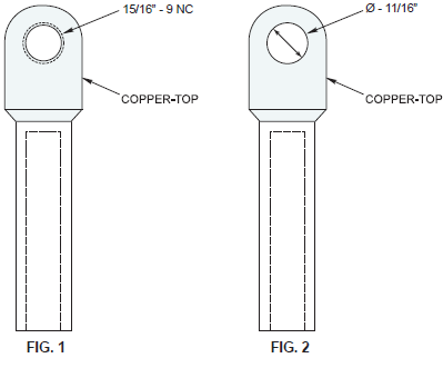
The connector shall be of bimetallic construction with an aluminum barrel and copper top.
8.4 Identification
The following information shall be permanently marked into each compression connector:
- Manufacturer's Name or Trademark
- Conductor Size
- Burndy Compression Die Size
8.5 Packaging
Each compression connector shall be individually packaged.
9. 600 Amp Elbow Terminator
9.1 Stock Code Numbers
This specification applies to the following District stock code numbers:
| Cable Size | Cable Insulation Dia. (Nominal) |
Stock Code No |
|---|---|---|
| 350 kcmil Al | 1.080" | 785412 |
| 1000 kcmil Al | 1.545" | 785420 |
9.2 General
Elbow terminators are used to connect medium voltage power cable to ANSI standard 8.3/15.2 kV 600 amp deadbreak interfaces on junction boxes, switchgear and other equipment. Elbow terminators shall be furnished with an integral 200 amp loadbreak interface, suitable for mounting 8.3/14.4 kV 200 amp loadbreak elbows manufactured in accordance with ANSI/IEEE 386. The 200 and 600 amp interfaces shall employ an all copper current path. The loadbreak reducing tap plug (LRTP) shall thread onto a 15/16" - 9 NC threaded bimetallic (copper top) compression connector creating a permanent assembly with the 600 amp elbow body. The elbow assembly shall mount on an ANSI standard 600 amp bushing via a 5/8" - 11 UNC 2A copper alloy threaded stud (Stk. No. 785529) and a rotating nut in the LRTP. The elbow assembly must be hot stick operable by one individual.
9.3 Construction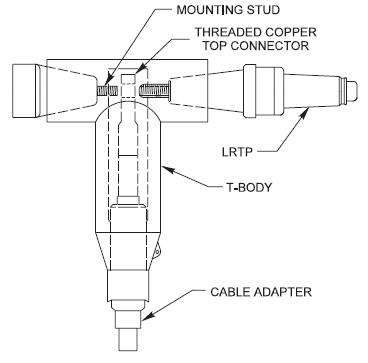
All rubber components, including the elbow body, conductive shield, stress relief, loadbreak reducing tap plug and conductive insert shall be molded of EPDM rubber.
9.4 Identification
The following information shall be molded into each 600 amp elbow housing:
- Manufacturer's Name or Trademark
- Date of Manufacture
- 600 Amp Continuous Current Rating
- 15.2 kV Voltage Rating
- The word "DEADBREAK"
9.5 Packaging
Each terminator assembly shall be individually packaged and shall include a 600 amp elbow housing, threaded bimetallic (copper top) compression lug, loadbreak reducing tap plug, copper bushing mounting stud, cable adapter and installation instructions.
10. 600/200 Amp Bushing Adapter
10.1 Stock Code Number
This specification applies to the following District stock code number: 785404
10.2 General
600/200 amp bushing adapters are used to convert an ANSI standard 8.3/15.2 kV 600 amp deadbreak interface to an ANSI standard 8.3/14.4 kV 200 amp loadbreak interface. The 200 and 600 amp interfaces shall employ an all copper current path. The bushing adapter shall mount on an ANSI standard 600 amp bushing via a 5/8" - 11 UNC 2A copper alloy threaded stud (Stk. No. 0785529) and a rotating nut in the LRTP. The bushing adapter assembly must be hot stick operable by one individual.
10.3 Construction
All rubber components, including the bushing extender, conductive shield, stress relief, loadbreak reducing tap plug and conductive insert shall be molded of EPDM rubber.
10.4 Drain and Ground Wires
The bushing adapter shall be provided with a #14 stranded copper drain wire and ground wire. The drain wire shall be pre-installed between the LRTP and bushing extender. The ground wire shall be attached to the bushing extender and shall be a minimum of 48 inches in length.
10.5 Identification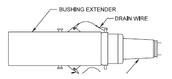
The following information shall be molded into each bushing adapter:
- Manufacturer's Name or Trademark
- Date of Manufacture
- 600 Amp Continuous Current Rating
- 15.2 kV Voltage Rating
- The word "DEADBREAK"
10.6 Packaging
Each bushing adapter shall be individually packaged and shall include the bushing extender complete with preinstalled LRTP, copper bushing mounting stud and installation instructions.
11. 600 Amp Connecting Plug
11.1 Stock Code Number
This specification applies to the following District stock code number: 776065
11.2 General
600 amp connecting plugs are used to connect two or more medium voltage power cables using ANSI standard 8.3/15.2 kV 600 amp deadbreak elbow connectors. 600 amp connecting plugs shall employ an all copper current path.
11.3 Construction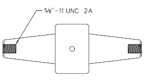
The connecting plug body shall be made of an insulating epoxy. All rubber components shall be molded of EPDM rubber.
11.4 Identification
The following information shall be molded into each connecting plug:
- Manufacturer's Name or Trademark
- Date of Manufacture
- 600 Amp Continuous Current Rating
- 15.2 kV Voltage Rating
- The word "DEADBREAK"
11.5 Packaging
Each connecting plug shall be individually packaged and shall include installation instructions.
12. 600 Amp Insulating Plug
12.1 Stock Code Number
This specification applies to the following District stock code number: 776106
12.2 General
600 amp insulating plugs are used in conjunction with 600 amp connecting plugs (Stk. No. 776065) to connect two or more medium voltage power cables using ANSI standard 8.3/15.2 kV 600 amp deadbreak elbow connectors.
600 amp insulating plugs shall be equipped with a threaded copper mounting stud (Stk. No. 785503), a 1" hex head capacitive test point and a semi-conducting EPDM rubber cap to provide a waterproof seal and deadfront shield over the test point.
12.3 Construction
The insulating plug body shall be made of an insulating epoxy. Insulating cap bail shall be stainless steel.
12.4 Identification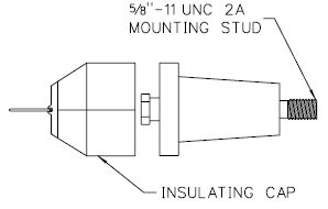
The following information shall be molded into each insulating plug:
- Manufacturer's Name or Trademark
- Date of Manufacture
- 600 Amp Continuous Current Rating
- 15.2 kV Voltage Rating
- The word "DEADBREAK"
12.5 Packaging
Each connecting plug shall be individually packaged and shall include installation instructions.
13. 600 Amp Insulated Standoff Bushing
13.1 Stock Code Number
This specification applies to the following District stock code number: 785511
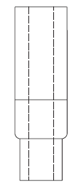
13.2 General
600 amp standoff bushings are used to provide an insulated interface for temporarily or permanently parking ANSI standard 8.3/15.2 kV 600 amp energized deadbreak connectors. Standoff bushings shall be designed for mounting on ANSI standard cable accessory parking stands. Each standoff bushing shall be equipped with a 5/8" - 11 UNC 2B copper alloy threaded stud (Stk. No. 0785529) designed for mounting elbow terminators and bushing adapters as described in Sections 9 and 10. Standoff bushings shall be designed for hotstick installation or removal.
13.3 Construction
The standoff bushing body shall be made of an insulating epoxy. All mounting hardware shall be stainless steel, except for the eyebolt pressure foot, which may be brass. The mounting bracket shall be equipped with a grounding lug for attaching up to a #2 bare stranded copper ground wire.
13.4 Identification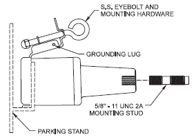
The following information shall be permanently marked into each standoff bushing:
- Manufacturer's Name or Trademark
- Date of Manufacture
- 600 Amp Continuous Current Rating
- 15.2 kV Voltage Rating
- The word "DEADBREAK"
13.5 Packaging
Each standoff bushing shall be individually packaged and shall include the standoff bushing complete with pre‑installed copper bushing mounting stud and installation instructions.
14. 600 Amp Insulated Protective Cap
14.1 Stock Code Numbers
This specification applies to the following District stock code number: 785454
14.2 General
600 amp insulated protective caps are used to provide insulated, fully shielded, submersible protection to an ANSI standard 8.3/15.2 kV 600 amp energized deadbreak interface. The insulated protective cap shall be designed for hotstick installation or removal on a de-energized bushing.
14.3 Construction
All rubber components, including the cap body and conductive shield shall be molded of EPDM rubber. Molded pulling eye shall be reinforced for hotstick operation.
14.4 Drain and Ground Wires
The bushing adapter shall be provided with a #14 stranded copper ground wire a minimum of 30 inches in length.
14.5 Identification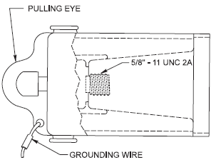
The following information shall be molded into each insulated protective cap:
- Manufacturer's Name or Trademark
- Date of Manufacture
- 600 Amp Continuous Current Rating
- 15.2 kV Voltage Rating
- The word "DEADBREAK"
14.6 Packaging
Each insulated protective cap shall be individually packaged and shall include the protective cap and installation instructions.
15. 600 Amp 4-Position Junction Box
15.1 Stock Code Number
This specification applies to the following District stock code number: 0762452
15.2 General
600 amp junction boxes are used to provide four ANSI standard 8.3/15.2 kV 600 amp deadbreak interfaces bused together and fitted to a bracket for mounting in vaults and above grade cabinets. The junction box shall employ an all copper current path.
15.3 Construction
All rubber components, including the junction body and conductive shield shall be molded of EPDM rubber.
15.4 Mounting Bracket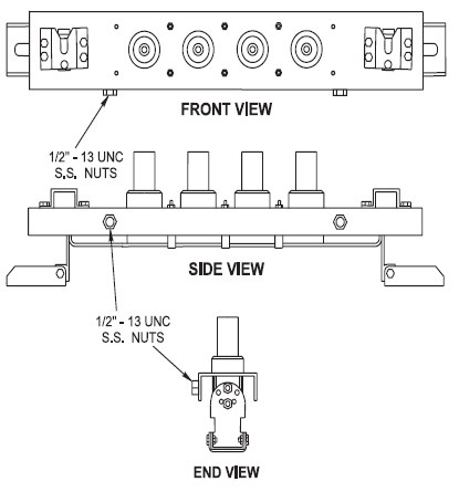
The junction box mounting bracket and all mounting hardware shall be manufactured from stainless steel. The mounting bracket shall be adjustable so the junction body can be tilted up to 45° from the horizontal in a minimum of 15° increments. The mounting bracket feet shall be adjustable for mounting on flat or curved surfaces.
Each mounting bracket shall be equipped with two ANSI standard cable accessory parking stands mounted on opposite ends of the bracket and oriented so that cable accessories remain parallel with the junction box bushings.
Each mounting bracket shall be equipped with two 1/2" ‑ 13 UNC stainless steel grounding nuts welded to the mounting bracket bottom lip as indicated in the adjacent drawing.
15.5 Identification
The following information shall be molded into each junction body:
- Manufacturer's Name or Trademark
- Date of Manufacture
- 600 Amp Continuous Current Rating
- 15.2 kV Voltage Rating
- The word "DEADBREAK"
15.6 Packaging
Junction boxes shall be shipped fully assembled in individual packages complete with installation instructions.
16. 600 Amp Deadbreak Terminator Installation Tools
16.1 T-Wrench (Stk. No. 0751900)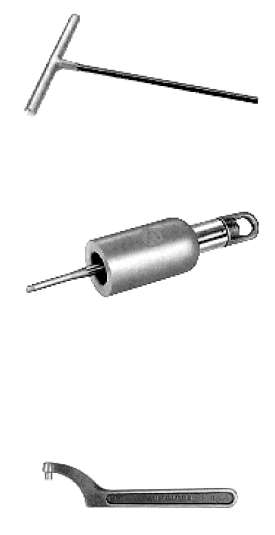
The 5/16" T-handled wrench is used to install Loadbreak Reducing Tap Plugs (LRTP) into bimetallic connectors for 600 amp elbow terminators as described in Section 8.
16.2 Operating and Testing/Torque Tool (Stk. No. 0751918)
The Operating and Testing/Torque Tool is used with a hotstick to test for circuit de‑energization and to install and remove 600 amp elbow terminators and 600/200 amp bushing adapters as described in Sections 8 and 9. The Operating and Testing/Torque tool is equipped with a molded EPDM cap to assist in tool seating and gripping the connector and an integral torque limiter pre-set to 20 inch-lb. installation torque. The Operating and Testing/Torque Tool is hot stick operable.
16.3 Spanner Wrench (Stk. No. 0751926)
The spanner wrench is required to assemble or disassemble 600 amp connecting tap plugs and insulating plugs from 600 amp T-bodies.