897720.3 Full Length Pressure Treated Laminated Wood Poles
Click here for a PDF of this Material Standard
Revision 3
Nov 15, 2013
1. Scope
This Material Standard describes the minimum acceptable requirements for full length pressure treated laminated wood poles produced for and delivered to the District as specified in the attached Special Provision Sheet. Where there is conflict between this Material Standard and any other standard referred to herein, this Material Standard shall govern.
2. Reference Standards
Except where provisions conflict with the requirements of this Material Standard, poles shall meet all applicable provisions of the latest revisions of the following standards:
AN SI O5.2-1996 (R2001) Wood Products - Structural Glued Laminated Timber for Utility Structures
AN SI/AITC A190.1 Standard for Wood Products - Structural Glued Laminated Timber
AITC 110 Standard Appearance Grades for Structural Glued Laminated Timber
AITC 111 Recommended Practice for Protection of Structural Glued Laminated Timber During Transit, Storage and Erection
AITC 117 Design Specifications for Structural Glued Laminated Timber of Soft Wood Species
AITC 200 Inspection Manual
AN SI/IEEE C2 National Electrical Safety Code
APA EWS S400 Proper Storage and Handling of Glulam Beams
AWPA Standard M6 Brands Used on Preservative Treated Materials
AWPA Standard U1 User Specification for Treated Wood
AWPA Standard T1 Processing and Treatment Standard
SPIB Standard Grading Rules for Southern Pine Lumber
WCLIPB WCLIB Standard Grading Rules No. 17
WWPA Western Lumber Grading Rules
3. General
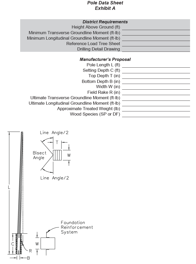
Pole requirements including quantity, dimensions, minimum transverse ground line capacity, minimum longitudinal ground line capacity and required above-grade pole height shall be specified in the special provisions sheet.
4. Lumber
4.1 Lumber shall be west coast region Douglas Fir or Southern Pine as defined in ANSI O5.2.
4.2 All laminating lumber shall be graded in accordance with all applicable grading rules of WCLIB or SPIB.
4.3 All lumber shall be free of timber breaks.
4.4 Decay of any form is not permitted, including decay in knots.
5. Design
5.1 Deflection
Field raked poles shall be designed so 60°F final, no wind wire tensions will deflect the pole top in-line with the pole face at ground line. Maximum rake shall be limited to 3% of the above-ground height. A field raking detail drawing shall be included with each pole.
5.2 Pole Length
Poles of such length that cannot be manufactured, treated or shipped in one piece shall be supplied in two pieces. Poles less than or equal to 90 feet in length shall be one piece. Poles greater than 90 feet in length may be two piece poles if approved by the District. All splice materials including bolts, nuts, washers, any other necessary hardware and instructions shall be individually packaged and labeled. Steel hardware shall be hot-dip galvanized per ASTM A123. Bolts, nuts, and washers delivered to the District shall include actual quantity plus 10% or a minimum of two bolt, nut, and washer assemblies per splice.
5.3 Pole Strength
Each pole data sheet (Exhibit A) shall include a load tree report indicating the location of each transverse, longitudinal and vertical load multiplied by the appropriate NESC Grade B load factor. Laminated pole strength reduced by the NESC Grade B strength factor shall meet or exceed the combined application of all specified loads without failure. On multi-section poles, splices shall be butt splices and shall develop at least 110% of the pole's moment capacity at the splice level.
5.4 Setting Depth
Nominal setting depth shall be 10% of pole length + 4 feet unless a deeper depth is required because of pole loads and/or soil conditions. Manufacturer shall specify design setting depths for each pole on the pole data sheet, Exhibit A. Setting depth shall be assumed based on crushed rock backfill unless a different backfill is required by the pole manufacturer.
5.5 Foundation Reinforcement
When required, poles shall be drilled and furnished with foundation reinforcement systems. Each foundation system shall be individually packaged, complete with all attachment hardware and labeled with the structure number for which the system is designed. Steel hardware shall be hot-dip galvanized per ASTM 123.
5.6 Pole Data Sheets
Each pole shall include data sheets with all appropriate installation information including framing, setting depth, hole diameter, backfill, and if appropriate, installation rake and foundation reinforcement.
6. Manufacturing
6.1 Framing
6.1.1 Framing drawings, including size and location of all bolt holes shall be attached to the special provisions sheet. Framing bolt assemblies shall be supplied by the District.
6.1.2 All bolt holes shall be parallel with or perpendicular to each other, as appropriate. All bolt holes shall be bored through the true axis of the pole using sharp drill bits. All bore holes shall be cleaned so they are completely open prior to treatment. Unless specified otherwise on the plans, holes shall be a minimum of 1/16" and a maximum of 1/8" larger than the bolt diameter.
6.1.3 Drilling and square cut roofing shall be done on all poles prior to treatment.
6.2 Incising
All poles shall be incised for the full pole length and on all four sides with a minimum depth of 5/8".
6.3 Through Boring
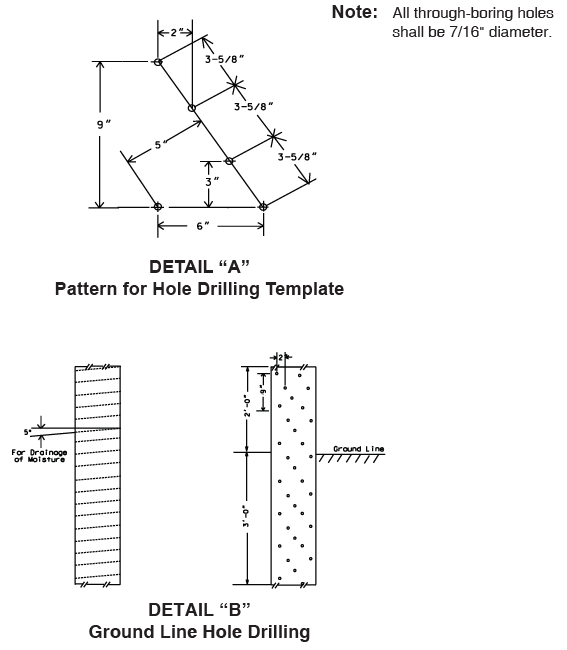
6.3.1 All poles shall be drilled for internal treatment in a zone 2.0 feet above and 3.0 feet below the intended ground line. The drilling patterns shall be in accordance with Details "A" & "B", shown below. Drilled holes on edge faces shall be omitted for the first two laminations on each side. Care shall be taken on the edge faces to ensure that drill holes do not penetrate along glue lines. Drilling shall be done carefully to avoid charring and glazing of the inner surfaces.
6.3.2 All poles constructed with Southern Pine shall be drilled on the two non-edge faces only.
6.4 Pole Dimensions and Tolerances
Sizes and tolerances for poles shall be in accordance with the following:
Depth: ± 1/2”
Width: ± 1/4”
Squareness per foot of depth: ± 3/8”
Length (poles under 50 feet): + 6” , - 3”
Length (poles over 50 feet): + 12” , - 6”
6.5 Pole Marking
Poles shall be marked in accordance with ANSI O5.2.
7. Treatment
7.1 Best Management Practices
Poles shall be treated in compliance with the Best Management Practices for the Use of Treated Wood in Aquatic and Wetland Environments (developed by the Western Wood Preservers Institute and other supporting organizations) and certified in compliance by a third party quality inspection agency.
7.2 Equipment
Plant treating equipment shall be in accordance with AWPA Standard T1.
7.3 Preservative
The preservative shall be copper naphthenate solution meeting the requirements of AWPA Standard T1 and shall not contain any chlorinated compounds.
7.4 Solvents and Co-Solvents
If an organic preservative system is used, the solvent and any co-solvents shall conform to AWPA Standard T1, Type A or Type C. Shall have the lowest concentration of polycyclic aromatic hydrocarbons (PAHs) possible, and shall not trigger the Washington Department of Ecology carcinogenic PAH testing requirement outlined under AC 173-340-900 (Table 830-1) or as otherwise determined by the Department of Ecology. The preservative, solvents and co-solvents shall not contain any chlorinated compounds.
7.5 Penetration
7.5.1 Glue laminated poles shall be treated in accordance with AWPA U1 and T1. Assay and penetration zones for glue laminated poles shall be in accordance with AWPA T1, Table 8.4.6, Use Category 4B.
7.5.2 Penetration shall be determined from increment borer cores taken 1 to 2 feet below the brand from each piece of the charge. Additional cores in the through bored zone shall be taken 1 foot above the intended ground line and 1 foot below the top of the drilled zone. If 90% of the boring meets the penetration requirements, the charge shall be accepted, but the non-conforming poles in the charge shall be retreated.
If more than four of the first twenty poles fail on penetration, the entire charge shall be rejected.
7.5.3 Penetration of copper naphthenate shall be not less than 0.75" from the surface for Douglas Fir and not less than 3.00" from the surface for Southern Pine. Penetration in the through boring zone shall be a minimum of 2-1/2" from the surface.
7.6 Retention
Preservative retention in glue laminated poles shall be in accordance with AWPA U1, Table 6.5, Use Category 4B. Minimum retention of preservative for full length pressure treated glue laminated poles shall be as shown below and as determined by the method described in AWPA A5, Section 7.
Pacific Coast Douglas Fir 0.095 pcf (Cu as metal) Outer zone 0.048 pcf (Cu as metal) Inner zone Southern Pine 0.080 pcf (Cu as metal)
7.7 Retreatment
Poles may be retreated once providing none of the retreatment limitations specified in AWPA T1, Section 6 are exceeded.
7.8 Cleanliness
After treatment, all poles shall be clean and dry, without excess surface oil, and shall remain in that condition. Bleeders will be rejected.
7.9 Color
Upon completion of the treating process, all poles shall be as light colored as reasonably possible to obtain a light to medium brown.
7.10 Appearance
Glued laminated members shall be manufactured in accordance with the industrial appearance grade as defined in AITC 110 and ANSI O5.2.
8. Testing and Inspection
8.1 Testing and inspection shall be in accordance with ANSI O5.2.
8.2 All poles shall be subject to incoming acceptance inspection. Any poles not conforming to the District's specifications shall be corrected or replaced at the District's discretion. All costs of any corrections or replacements will be at the Vendor's expense.
9. Storage and Shipping
9.1 Storage, shipping and handling shall be in accordance with AITC 111.
9.2 The foundation system for each pole shall be individually packaged and labeled, complete with all attachment hardware.