897720.1 (Obsolete) Full Length Penta Pressure Treated Wood Poles
Click here for a PDF of this Material Standard
Revision 3
Sep 23, 2011
1. Scope
This Material Standard describes the minimum acceptable requirements for full length pressure treated Pacific Coast Douglas Fir and Western Red Cedar poles produced for and delivered to the District as specified in the attached Special Provision Sheet. Where there is conflict between this Material Standard and any other standard referred to herein, this Material Standard shall govern.
Unless otherwise specified by the District, poles supplied under this Material Standard shall be produced by plants currently approved by Wood Quality Control (WQC), Incorporated.
2. Reference Standards
Except where provisions conflict with the requirements of this Material Standard, poles shall meet all applicable provisions of the latest revisions of the following standards:
ANSI O5.1 Specifications and Dimensions for Wood Poles
AWPA A5 Standard Methods for Analysis of Oil-Borne Preservatives
AWPA M1 Standard for the Purchase of Treated Wood Products
AWPA M2 Standard for Inspection of Wood Products Treated with Preservatives
AWPA M4 Standard for the Care of Preservative-Treated Wood Products
AWPA P8 Standard for Oil-Borne Preservatives
AWPA P9 Standards for Solvents and Formulations for Organic Preservative Systems
AWPA T1 Use Category System: Processing and Treatment Standard, 8.D. Special Requirements - Poles
AWPA U1 Use Category System: User Specification for Treated Wood, 6.D. Commodity Specifications - Poles
3. Definitions
ANSI American National Standards Institute
AWPA American Wood Protection Association
WCLIB West Coast Lumber Inspection Bureau
4. Dimensions
The length and class of poles to be provided will be specified in the attached Special Provision Sheet.
4.1 Length
Poles less than 50-feet in length shall be not more than 3-inches shorter or 6-inches longer than nominal length.
Poles 50-feet or more in length shall be not more than 6-inches shorter or 12-inches longer than nominal length.
Pole length shall be measured between the extreme ends of the pole.
4.2 Circumference
The circumferences for the class of poles specified by the District shall conform to the requirements specified in ANSI O5.1, Section 6.2.2.
4.3 Classification
The true pole circumference class shall be determined as specified in ANSI O5.1, Section 6.3.
5. Rate of Growth
The average rate of growth measured on the butt in the outer 3-inches shall be not less than six rings per inch. The only exception is that poles with four and five rings per inch will be acceptable if 50-percent or more summerwood is present.
6. Prohibited Defects
Poles shall be free of the following defects, as defined in ANSI O5.1:
6.1 Cross Breaks (Cracks)
6.2 Decay, except as permitted for firm red heart, defective butts, and decayed knots in ANSI O5.1, Sections 5.3.1, 5.4.4 and 5.4.6, respectively
6.3 Dead Streaks, except as permitted in ANSI O5.1, Section 5.4.3
6.4 Holes, open or plugged, except holes for test purposes, which shall be plugged with a treated plug
6.5 Hollow Butts or Tops
6.6 Marine Borer Damage
6.7 Nails, Spikes, and Other Metal not specifically authorized by the District
7. Limited Defects
The following limited defects will be allowed, as defined in ANSI O5.1:
7.1 Bark Inclusions
7.2 Compression Wood
7.3 Dead Streaks
7.4 Defective Butts
7.5 Insect Damage
7.6 Knots
Knots shall be permitted as defined in ANSI O5.1 with the following clarifications:
7.6.1 The diameter of any single knot and the sum of knot diameters in any 1-foot section shall not exceed the limits stated in ANSI O5.1, Table 2.
7.6.2 In determining the sum of the knot diameters in any 1-foot section, only those knots with diameters greater than 1/2-inch shall be included in the sum, and the 1-foot section shall be located so as to include the maximum number of knots, i.e., the most severe condition.
7.6.3 As defined in ANSI O5.1, Section 3.11, Type I decayed knots are not permitted; Type II decayed knots are permitted.
7.7 Scars
7.8 Shakes
7.9 Shape
Poles shall be shaped in accordance with ANSI O5.1, with the exception that poles with sweep in 2 planes (double sweep) will not be accepted.
7.10 Spiral Grain
Poles having spiral grain (twist grain) in excess of one complete twist in any 20-foot length of pole will not be accepted. This restriction applies to all pole lengths.
7.11 Splits and Checks
7.11.1 Check Width: No check shall exceed 1/2-inch in width.
7.11.2 In the Top: A split or a combination of two single checks (each check terminating at the pith center and separated by not less than 1/6 of the pole circumference) having one or both portions located in a vertical plane within 30-degrees of the top hole shall not extend downward along the pole more than 6-inches.
All other single checks, combinations of checks, or a split shall not extend downward along the pole more than 12-inches.
7.11.3 In the Body: The maximum length of a check, having a width equal to, but not greater than 1/2-inch, shall be 3-feet, as measured from the maximum width (1/2-inch) to the bottom of the check. No continuous check of any width shall extend more than 1/5 the length of the pole. A check shall be considered continuous if it is not separated by at least 3/8-inch of wood.
7.11.4 In the Butt: A split, a single check, or a combination of two single checks, as defined above, shall not extend upward along the pole more than 2-feet.
7.12 Correction of Split Top
Upon mutual agreement between the pole manufacturer and the independent inspector, an anti-splitting device, such as a Star-Lock, may be used to prevent a pole from becoming a reject due to a split or check(s) in its top. An anti-splitting device shall not be used to correct a pole top after a pole has been rejected due to a split or check(s) in its top. The size and type of anti-splitting device required shall be determined jointly by the pole manufacturer and the independent inspector.
8. Permitted Defects
The following defects are permitted as defined in ANSI O5.1:
8.1 Firm Red Heart
8.2 Sap Stain
9. Manufacturing Requirements
All work shall be performed by skilled craftsmen following the best modern practices of the industry.
9.1 Bark Removal
Bark shall be removed in accordance with ANSI O5.1.
9.2 Sawing
9.2.1 All poles shall be neatly sawn at the butt along a plane which shall not be out of square with the axis of the pole by more than 2-inches per foot of diameter of the sawed surface. Beveling at the edge of the sawn butt surface not more than 1/12 the butt diameter in width, or an equivalent area unsymmetrically located, is permitted.
9.2.2 All poles shall be neatly sawn at the top with a single saw cut. The pole top shall be flat across with no slope, i.e., sawn at a right angle to the face of the pole.
9.3 Trimming
Trimming shall be in accordance with ANSI O5.1.
9.4 Incising
9.4.1 The ground line of the pole shall be defined as shown in Table 2 on page 12 of this Material Standard.
9.4.2 Douglas Fir poles shall be incised 1/2-inch minimum depth for the entire length of the pole prior to treatment.
9.4.3 Western Red Cedar poles shall be incised throughout that portion of the pole surface terminating 1-foot above and 2-feet below the ground line prior to treatment.
9.4.4 Incisions shall be reasonably clean cut and their spacing, pattern and depth shall be made so as to ensure uniform penetration of the preservative to the required depth throughout the incised area.
9.4.5 The sapwood shall not be splintered or loosened from the heartwood in the incising operation.
9.5 Through-Boring to Enhance Preservative Penetration
9.5.1 The ground line area and top 2 ft of Douglas Fir poles shall be through-bored prior to treatment to enhance penetration of the preservative into the pole per the requirements of this Material Standard, reference:
- Detail “A” Pattern for Through-Boring Template (page 11)
- Detail "B" Ground Line Through-Boring Pattern (page 11)
- Table 1 Through-Boring Instructions (page 12)
- Table 2 Ground Line Distance from Butt (page 12)
9.5.2 Through-boring will not be required for full-length pressure treated Western Red Cedar poles.
9.5.3 Through-boring shall be done carefully to avoid charring or glazing of the inner surfaces.
9.5.4 All holes shall be completely bored through the pole from one direction.
9.5.5 All ground line through-boring shall be done on the face of the pole and all pole top through-boring shall be done at 45-degrees to the face of the pole.
9.6 Marking
9.6.1 The butt of all poles shall be marked with a flooring axe bearing the 3/4-inch block letters “P.U.D.” The length, in feet, of each pole shall be clearly marked on the butt in the same manner.
9.6.2 Each pole shall be marked as specified in ANSI O5.1 by two aluminum or stainless steel discs. Each disc shall have stamped or embossed thereon the supplier's code or trademark; the plant location and the year of treatment; code letters denoting the pole species and preservative used; and the true circumference-class numeral and numerals showing the length of the pole. The discs shall be approximately 2-inches in diameter. The discs shall be punched with a nail hole, placed in the marking disc recesses on the pole face and butt, and attached with 2-inch aluminum twist nails.
9.6.3 The top of each pole shall have a permanent aluminum or stainless steel tag attached, which shall be marked to indicate that the pole is treated with pentachlorophenol.
9.7 Butt Gain
A neatly cut gain 2-inches wide and 1/2-inch deep (at its center) shall be provided on the face of the pole at the distance given below. This distance shall be measured from the butt of the pole to the center of the gain. The face of the pole shall be as defined in ANSI O5.1.
| Length of Pole | Distance of Butt Gain from Bottom of Pole |
|---|---|
| Less than or equal to 85 ft | 12 ft |
| Greater than 85 ft | 15 ft |
9.8 Framing
9.8.1 Additional gains shall be cut and holes bored in accordance with Figures 1 through 4 which correspond to the pole length specified in the attached Special Provision Sheet. All gains shall be neatly cut and bore holes shall be neatly drilled and cleaned so that they are completely open.
| Figure | Length of Pole |
|---|---|
| 1 | 30 ft, 35 ft |
| 2 | 40 ft, 45 ft, 50 ft, 55, 60 ft |
| 3 | 30 ft Class 6 Yard Light Pole |
| 4 | 65 ft and Longer |
9.8.2 All gains shall be cut and holes bored before poles are treated.
9.8.3 All gains shall be cleanly and neatly cut.
9.8.4 All bolt holes shall be parallel with or perpendicular to each other, as appropriate. All bolt holes shall be bored through the true axis of the pole using sharp drill bits. All bore holes shall be cleaned so they are completely open prior to treatment
FIGURE 1: Framing Details for 30 and 35 ft Poles
1. Any pole having a curvature or sweep shall be gained on the inside of the sweep so that when the pole is set the curvature will be parallel with the pole line.
2. The Butt Gain shall be in the same plane and at right angles to bolt holes.
3. The Butt Gain shall be 2” wide with a center depth of 1/2”.
4. After treatment, bolt hole diameters shall be as shown below:
| Pole Length | Bolt Hole Dia. |
|---|---|
| 30 ft | 13/16" |
| 35 ft | 11/16" |
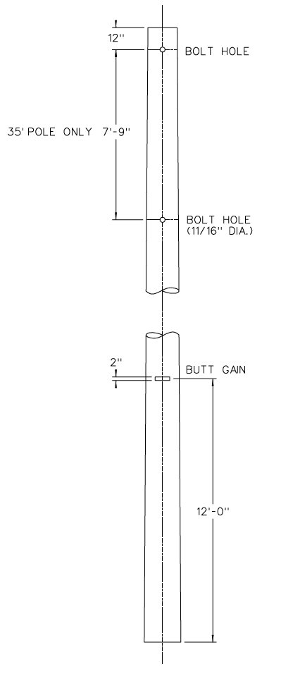
FIGURE 2: Framing Details for 40, 45, 50, 55 and 60 ft Poles
- Any pole having a curvature or sweep shall be gained on the inside of the sweep so that when the pole is set the curvature will be parallel with the pole line.
- Gains shall be in the same plane and at right angles to bolt holes.
- The Crossarm Gain shall be 6” wide. Depth shall be not less than 5/8” nor more than 3/4”. Center of gain shall be 1/4” deeper than edges.
- The Butt Gain shall be 2” wide with a center depth of 1/2”.
- After treatment, all bolt holes shall have a diameter of 11/16” minimum, 13/16” maximum, except as otherwise indicated on the drawing.
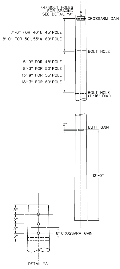
FIGURE 3: Framing Details for 30 ft Class 6 Yard Light Pole
- Any pole having a curvature or sweep shall be gained on the inside of the sweep so that when the pole is set the curvature will be parallel with the pole line.
- The Butt Gain shall be 2” wide with a center depth of 1/2”.
- After treatment, all bolt holes shall have a diameter of 11/16” minimum, 13/16” maximum.
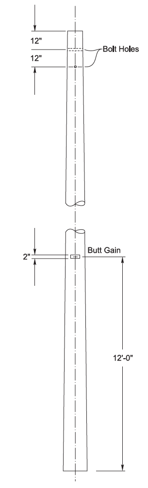
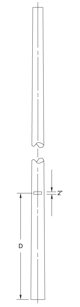
FIGURE 4: Framing Details for Poles 65 ft and Longer
- Any pole having a curvature or sweep shall be gained on the inside of the sweep (pole face) so that when the pole is set the curvature will be parallel with the pole line.
- The Butt Gain shall be 2” wide with a center depth of 1/2”.
- The distance from the butt to the center line of the gain shall be as shown below:
| Pole Length | Dimension D |
|---|---|
| 65 - 85 ft | 12 ft |
| > 85 ft | 15 ft |
10. Conditioning
10.1 Poles shall be seasoned to condition the wood for treatment in a manner that does not damage the wood in accordance with the applicable parts of ANSI O5.1, section 5 and AWPA M1-11, section 1.3 unless otherwise specified herein. Seasoning shall be by the Boulton drying method or a combination of Boulton drying with air seasoning or kiln drying.
10.2 The moisture content of seasoned poles shall be less than 30-percent before the poles are treated.
10.3 During final seasoning by Boulton drying, the temperature shall be limited to 220°F for Pacific Coast Douglas Fir in accordance with ANSI O5.1, Section 5.1.2.2.
10.4 Sterilization
In accordance with the requirements of ANSI O5.1, Section 5.1.2.6, sterilization shall occur during the seasoning or treating process and certification of its occurrence shall be readily available.
11. Treatment
11.1 Best Management Practices
Poles shall be treated in compliance with the Best Management Practices for the Use of Treated Wood in Aquatic Environments, (Western Wood Preservers Institute 1996) and certified in compliance by a third party quality inspection agency.
11.2 Preservative
The preservative shall be pentachlorophenol oil-borne solution meeting the requirements of AWPA P8 and P9.
11.3 Solvents and Co-Solvents
If an organic preservative system is used, the solvent and any co-solvents shall conform to AWPA P9 Type A. The solvent and any co-solvents shall have the lowest concentration of polycyclic aromatic hydrocarbons (PAHs) possible, and shall not trigger the Washington Department of Ecology carcinogenic PAH testing requirement outlined under WAC 173-340-900 (Table 830-1) or as otherwise determined by the Department of Ecology.
11.4 Penetration
Poles in each charge shall be bored to check for penetration of the preservative in accordance with the requirements of AWPA T1.
11.4.1 For Douglas Fir poles the minimum penetration of preservative shall be 100-percent in the top throughbored zone and ground line through-bored zone. Skips of up to two rings in the inner-most third of the core are allowed.
11.4.2 For all other areas outside the through-bored zones, penetration of preservative in the sapwood for Douglas Fir poles shall be a minimum of 0.75-inch (and 85-percent of the sapwood).
11.4.3 For Western Red Cedar poles, penetration of preservative in the sapwood shall be a minimum of 0.5-inch (or 100-percent of the sapwood).
11.5 Retention
Treating shall be by the empty-cell process in accordance with AWPA U1, Use Category 4B. Minimum retention of preservative for full length pressure treated poles shall be as shown below and as determined by the method described in AWPA A5, Section 5.
| Pacific Coast Douglas Fir | 0.45 pcf Outer Zone (0.25" - 1.0") 0.23 pcf Inner Zone (2.0" - 2.5") |
| Western Red Cedar | 1.0 pcf |
11.6 Retreatment
Poles may be retreated once providing none of the retreatment limitations specified in AWPA T1, Section 6 are exceeded.
11.7 Cleanliness
After treatment all poles shall be clean and dry (moisture content shall be 25-percent or less) and shall remain in that condition. Bleeders will be rejected.
12. Storage and Handling
Storage and handling of poles shall be in accordance with ANSI O5.1.
13. Inspection
Poles shall be inspected in accordance with the requirements of the Wood Quality Control (WQC) program.
14. Rejection
Poles not conforming to this Material Standard and poles received bleeding, damaged or broken will be rejected.
The supplier shall appropriately dispose of rejected poles at supplier’s own expense.
15. Delivery
15.1 Poles shall be delivered to and unloaded at any storage site within the District's service area as specified in the attached Special Provision Sheet.
15.2 All shipments shall arrive at the District with capabilities for self-unloading, i.e., shall have a self-sufficient means of unloading.
16. Evaluation of Bids
All bids will be evaluated on delivery schedules, initial costs, escalations, past performance of supplier and product quality.
17. General Bidding Conditions
The attached General Bidding Conditions are made a part of this Material Standard.
| Pole Diameter (in.) |
Number of Rows at 2 in. Spacing |
Edge Distance (in.) |
Pole Diameter (in.) |
Number of Rows at 2 in. Spacing |
Edge Distance (in.) |
|---|---|---|---|---|---|
| 8 | 3 | 2 | 15 | 7 | 1-1/2 |
| 8-1/4 | 3 | 2-1/8 | 15-1/4 | 7 | 1-5/8 |
| 8-1/2 | 3 | 2-1/4 | 15-1/2 | 7 | 1-3/4 |
| 8-3/4 | 3 | 2-3/8 | 15-3/4 | 7 | 1-7/8 |
| 9 | 4 | 1-1/2 | 16 | 7 | 2 |
| 9-1/4 | 4 | 1-5/8 | 16-1/4 | 7 | 2-1/8 |
| 9-1/2 | 4 | 1-3/4 | 16-1/2 | 7 | 2-1/4 |
| 9-3/4 | 4 | 1-7/8 | 16-3/4 | 7 | 2-3/8 |
| 10 | 4 | 2 | 17 | 8 | 1-1/2 |
| 10-1/4 | 4 | 2-1/8 | 17-1/4 | 8 | 1-5/8 |
| 10-1/2 | 4 | 2-1/4 | 17-1/2 | 8 | 1-3/4 |
| 10-3/4 | 4 | 2-3/8 | 17-3/4 | 8 | 1-7/8 |
| 11 | 5 | 1-1/2 | 18 | 8 | 2 |
| 11-1/4 | 5 | 1-5/8 | 18-1/4 | 8 | 2-1/8 |
| 11-1/2 | 5 | 1-3/4 | 18-1/2 | 8 | 2-1/4 |
| 11-3/4 | 5 | 1-7/8 | 18-3/4 | 8 | 2-3/8 |
| 12 | 5 | 2 | 19 | 9 | 1-1/2 |
| 12-1/4 | 5 | 2-1/8 | 19-1/4 | 9 | 1-5/8 |
| 12-1/2 | 5 | 2-1/4 | 19-1/2 | 9 | 1-3/4 |
| 12-3/4 | 5 | 2-3/8 | 19-3/4 | 9 | 1-7/8 |
| 13 | 6 | 1-1/2 | 20 | 9 | 2 |
| 13-1/4 | 6 | 1-5/8 | 20-1/4 | 9 | 2-1/8 |
| 13-1/2 | 6 | 1-3/4 | 20-1/2 | 9 | 2-1/4 |
| 13-3/4 | 6 | 1-7/8 | 20-3/4 | 9 | 2-3/8 |
| 14 | 6 | 2 | 21 | 10 | 1-1/2 |
| 14-1/4 | 6 | 2-1/8 | 21-1/4 | 10 | 1-5/8 |
| 14-1/2 | 6 | 2-1/4 | 21-1/2 | 10 | 1-3/4 |
| 14-3/4 | 6 | 2-3/8 | 21-3/4 | 10 | 1-7/8 |
Notes:
- All ground Line through-boring shall be done on the face of the pole, and all pole top through-boring shall be done at 45 degrees to the face of the pole.
- The pole top through-boring pattern shall be similar to Detail "B" but shall extend only 2 feet down from the top of the pole.
- All through-boring shall be done prior to treatment.
- All holes shall be completely bored through from one direction.
| Pole Length (ft) | 30 | 35 | 40 | 45 | 50 | 55 | 60 | 65 | 70 | 75 | 80 | 85 | 90 | 95 | 100 | 105 | 110 | 115 |
| Ground Line (ft) | 5.0 | 5.5 | 6.0 | 6.5 | 7.0 | 7.5 | 8.0 | 8.5 | 9.0 | 9.5 | 10.0 | 10.5 | 11.0 | 11.5 | 12.0 | 12.5 | 13.0 | 13.5 |