711300.1 Self-Supporting, Direct Buried Fiberglass Street Light Pole
Click here for a PDF of this Material Standard
Revision 11
Aug 17, 2018
1. Scope
This specification applies to round tapered single piece self-supporting, direct-buried fiberglass street light pole. This pole shall meet all the strength requirements of local, state, and national safety codes, assuming a 90 M.P.H. wind loading condition. Pole shall accommodate mounting of the 6' mast arm defined by District Material Standard No. 1000984.1, latest revision.
2. Material ID Number
This specification applies to the following District Material ID Number: 711300
3. Reference Standards
Poles supplied under this Specification shall conform to the characteristics, definitions, terminology, and requirements of the latest editions, amendments, and supplements of the applicable parts of the following standards, except as otherwise specified herein.
ANSI C136.20 - Fiber Reinforced Plastic (FRP) Lighting Poles for Use on Roadway Lighting
ASTM A 153 - Zinc Coating (Hot Dip) on Iron and Steel Hardware
ASTM D 635 - Flame Resistance
NEMA SH4 - Luminaire Attachments
4. Pole Length, Setting Depth and Weight
Refer to “Exhibit B”, Framing Requirements.
The overall length of the pole shaft shall provide a 30' nominal luminaire mounting height above final grade surface on a tapered oval 6' aluminum mast arm with a 24" rise.
The pole shall require a 5' maximum setting depth in class 5 soil.
The maximum weight of the pole shall not exceed 130 pounds.
5. Final Grade Depth and Marking
The final grade setting depth shall be 48" below the center of the wire access handhole and shall be marked with a transparent removable tape. Tape shall be 1"- 2" in height and at least 12" in length.
The wording “Final Grade” shall be printed on the tape as a quick guide to identify the proper setting depth of the pole.
The tape adhesive shall provide for easy removal without damaging finish of pole, however, the adhesive shall be adequate to adhere tape to pole during initial shipment and delivery to job site without falling off.
6. Pole Loading
The pole shall sustain a lateral load of 250 pounds applied at the top of the pole in any direction without failure of any component part and with the deflection of not more than 12% plus or minus 1% of the height of the pole from the ground line to top.
The pole shall sustain a vertical load of 250 pounds applied at the free end of the luminaire mast arm without collapse or rupture of any portion of the structure.
At the end of the 6' tapered oval aluminum luminaire mast arm mounting bracket, the pole shall sustain a vertical load of 100 pounds applied with the vertical deflection of not more than 5% of the bracket length; at the same point the pole shall sustain a horizontal load of 50 pounds applied in either direction with a horizontal deflection of not more than 7-½% of the bracket length.
7. Pole Identification
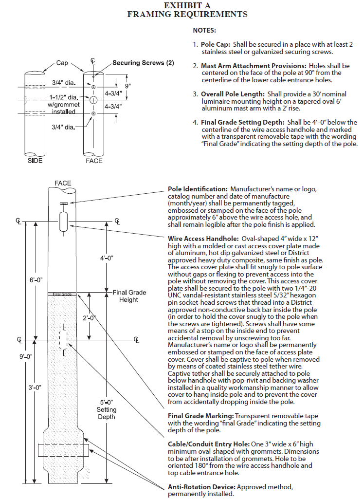
Refer to “Exhibit A”, Framing Requirements.
The manufacturer’s name or logo, catalog number and date of manufacture (month/year) shall be permanently tagged, embossed or stamped on the face of the pole approximately 6" above the wire access handhole. Tag identification shall remain legible after pole finish is applied. Tags shall be secured with aluminum pop-rivets. The stem of each rivet shall not protrude past the outer lip of the rivet causing a potential safety hazard.
8. Flame Resistance
The pole shall be flame resistant in accordance with ASTM D 635.
9. Pole Cap
Each pole shall include a cast aluminum, hot dip galvanized steel or heavy duty District approved fiberglass pole cap.
Caps shall fit snugly and shall be shipped securely attached to poles with at least two stainless steel or galvanized securing screws.
Metal caps shall not be painted. Fiberglass caps shall be same finish as pole.
10. Mast Arm Attachment Provision
Refer to “Exhibit A”, Framing Requirements.
The pole shall be delivered pre-drilled as specified to accommodate a 6' tapered oval aluminum luminaire mast arm with a 24" rise.
11. Wire Access Handhole
Refer to “Exhibit A”, Framing Requirements.
Each pole shall have one 4" wide x 12" high oval-shaped wire access handhole on the face side of the pole. The center of each access handhole shall be located 4'-0" above the Final Grade and 6'-0" above the center of the cable entrance hole.
Each handhole shall be provided with a molded or cast access cover plate made of aluminum, hot dip galvanized steel or District approved heavy duty composite, same finish as pole. The access cover plate shall fit snugly to pole surface without gaps or flexing to restrict access into the pole without removing the cover. This access cover plate shall be secured to the pole with two, ¼"-20 UNC stainless steel vandal-resistant 5/32" hexagon pin socket screws that thread into a District approved non-conductive back bar inside the pole in order to hold the cover snugly to the pole when the screws are tightened. The handhole cover screws shall have some means of a stop on the inside end to prevent accidental removal from unscrewing too far.
When the cover is removed for access inside the pole, the cover shall be held captive to the pole by means of a coated stainless steel tether wire, approximately 15" in length. Tether wire shall be securely attached to the pole with an aluminum pop-rivet and backing washer. The location of the pop-rivet on the pole shall be just below the handhole opening and shall not conflict with the access cover. The aluminum pop-rivet and backing washer shall be installed in a quality workmanship manner to allow the cover to hang from the tether inside the pole and to prevent the tether from being pulled loose and the cover from being accidentally dropped inside the pole. The stem of each rivet shall not protrude past the outer lip of the rivet causing a potential safety hazard.
The manufacturer’s name or logo shall be permanently embossed or stamped on the face of access cover plate.
12. Cable Holes
Refer to “Exhibit A”, Framing Requirements.
The pole shall have one round shaped cable entrance hole near the top on the face side of the pole that will provide direct access to the inside of the mast arm. This hole shall have an inside dimension of 1-½" with a tolerance of +½"/-0" after the grommet is installed and be centered between the mast arm mounting holes and 9" below the top of the pole.
The pole shall have one oval shaped cable/conduit entrance hole centered 36" from the bottom of the pole, 72" below the center of the wire access handhole specified in Section 11 and positioned 180° from the face. This hole shall have a minimum inside dimension of 3" wide x 6" high.
All cable hole openings shall be fitted with grommets to protect the electrical conductors from damage due to the abrasive edges of the holes. All grommets shall be installed with an adhesive to secure them during shipping, handling and installation of the pole.
The dimensions of all cable hole measurements specified above shall be after the grommets are installed.
13. Pole Stability
Refer to “Exhibit A”, Framing Requirements.
Pole shall have a permanently installed anti-rotational device (flared base, or other District approved permanently installed method) to provide resistance to rotation and pullout.
14. Finish
All poles furnished under this Material Standard shall have aesthetically pleasing surfaces and shall be free from imperfections, discolorations and stains.
The outer surface of the pole shall have a polyester surface veil cloth to extend the life of the pole.
The laminate (resin) shall contain colored pigment to match the finish coat of the pole. Solid coloration shall be throughout the entire wall thickness of the pole.
The pole finish shall have a smooth finish that resembles a polished surface. The final surface shall be free of all nubs, bristles roughness or imperfections and shall be uniform and consistent the entire length of the pole.
The finish coating shall be a light gray in color per ANSI Z55.1, No. 70, pigmented solvent base polyurethane finish for maximum resistance to deterioration from exposure to ultraviolet light, chemicals and extreme weather conditions.
The finish coating shall have a minimum dry film thickness of 1-½ mils.
15. Pole Interior
Pole interior shall be completely free of all wrapping, dust, fiberglass shavings and other preparation products to allow a clear and unobstructed path for installation of the wiring conductors.
16. Pole Packaging and Delivery
Each pole shall be individually wrapped in a 4 mil opaque plastic bag to protect them from dirt, grime, diesel smoke, etc. Bag shall be sealed or otherwise secured to pole to keep bag from tearing or blowing off in transit.
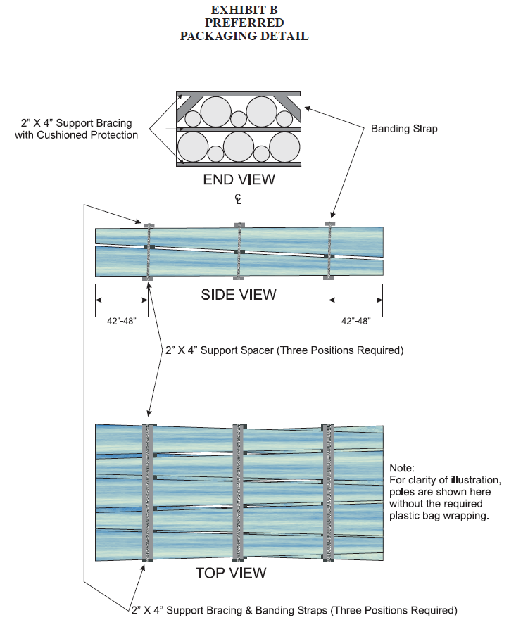
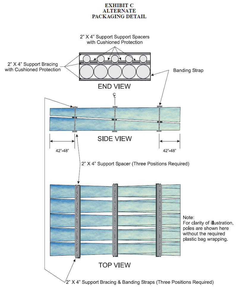
Poles shall be shipped ten to a bundle. Poles shall be arranged five across and two deep.
The preferred method of packaging poles for shipping is shown in “Exhibit B” Packaging Detail. The alternate method of packaging poles for shipping is shown in “Exhibit C” Packaging Detail, if the poles are properly packaged as shown.
The preferred method of secuing pole bundles shall be by using cushioned 2" x 4" support braces and 2" x 4" cushioned support spacer located in-between each layer of poles at each bracing/banding strap location to eliminate poles rubbing together or shifting during shipments. Positions of the bracing and banding shall be approximately 42" to 48" from each end and one in the center of the bundle. Any shipment of poles arriving with shipment damage are subject to the entire shipment being refused without unloading.
Pole bundles shall be easily loaded and unloaded by forklift without damage to the poles.
17. Bidders' Data
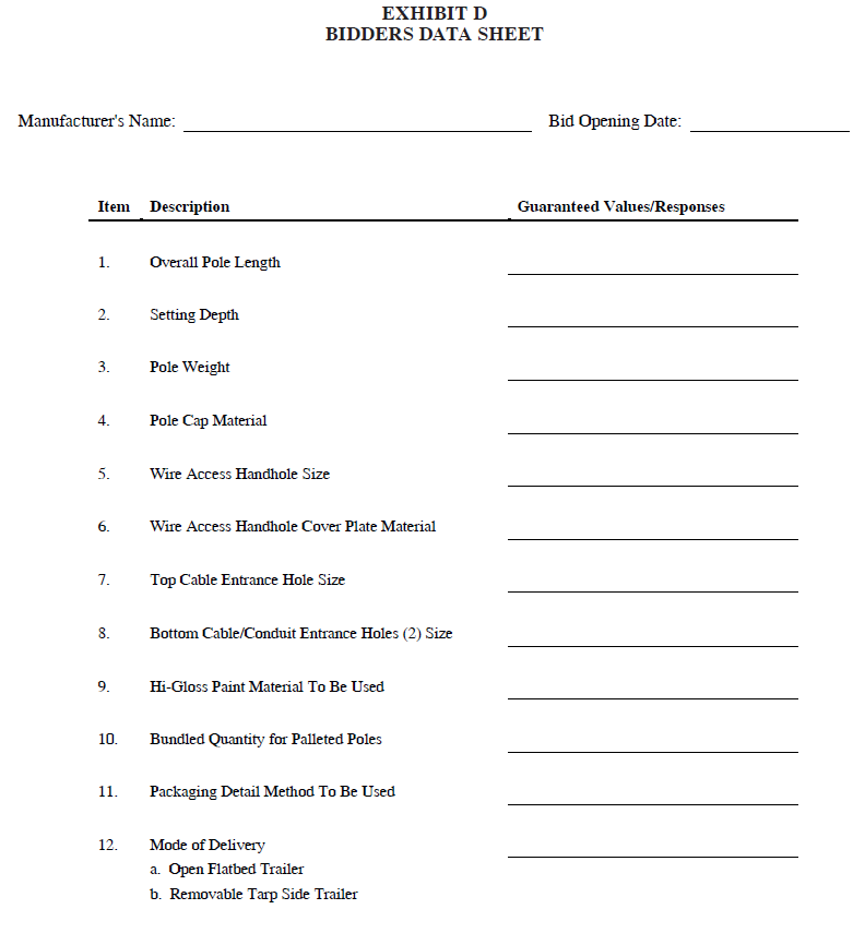
Each bidder shall submit an outline drawing of pole including all dimensions. Each bidder shall also submit with their proposal complete data and information as requested in Exhibit “D” of this Standard. A description of any proposed changes, additions or exceptions to the Standard, shall be submitted along with reasons for the departure.
18. Evaluation of Bids
The following factors will be considered in the analysis and evaluation of bids and subsequent bid award:
- Adherence to Standard
- Quality of product
- Past performance of Product and Bidder
- Proposed delivery
- Per unit bid price
19. General Bidding Conditions
The attached General Bidding Conditions in Exhibit “D” of this Standard are made a part of this specification.