1001408.1 Fiber-Reinforced Polymer Transmission and Distribution Poles
Click here for a PDF of this Material Standard
Revision 16
Dec 16, 2020
1. Scope
This specification applies to round tapered self-supporting, and/or guyed, direct-buried Fiber-Reinforced Polymer (FRP) poles.
2. Reference Standards
Unless otherwise stated in this specification, FRP poles shall comply with the latest revisions of the following standards:
District Standards
T&D Guideline 4-5-30.0 Fiberglass Distribution Poles
Industry Standards
ANSI C2 National Electrical Safety Code (NESC)
ANSI O5.1-2017 Specifications and Dimensions (for Wood Poles)
ASCE Recommended Practice for Fiber-Reinforced Polymer Products for Overhead Utility Line Structures, First Edition
ASTM D578 Standard Specification for Glass Fiber Strands
ASTM D4923 Standard Specification for Reinforced Thermosetting Plastic Poles
ASTM G154 Standard Specification for Operating Fluorescent Ultraviolet (UV) Lamp Apparatus for Exposure of Nonmetallic Materials
3. Material ID Numbers
This specification applies to the following District Material ID Numbers:
| Cat. ID | Description |
|---|---|
| 1001475 | Pole 35 ft Class 2 Fiber-Reinforced Polymer |
| 1001408 | Pole 45 ft Class 2 Fiber-Reinforced Polymer |
| 1001476 | Pole 50 ft Class 1 Fiber-Reinforced Polymer |
| 1002944 | Pole 50 ft Class H2 Fiber-Reinforced Polymer |
| 1001477 | Pole 55 ft Class 1 Fiber-Reinforced Polymer |
| 1001945 | Pole 55 ft Class H2 Fiber-Reinforced Polymer |
| 1002265 | Pole 60 ft Class 1 Fiber-Reinforced Polymer |
| 1002282 | Pole 60 ft Class H2 Fiber-Reinforced Polymer |
| 1002449 | Pole 65 ft Class 1 Fiber-Reinforced Polymer |
| 1002450 | Pole 65 ft Class H2 Fiber-Reinforced Polymer |
| 1003473 | Pole 70 ft Class 1 Fiber-Reinforced Polymer |
| 1003678 | Pole 70 ft Class H2 Fiber-Reinforced Polymer |
| 1002894 | Pole 75 ft Class H2 Fiber-Reinforced Polymer |
| 1003005 | Pole 80 ft Class 1 Fiber-Reinforced Polymer |
| 1003006 | Pole 80 ft Class H2 Fiber-Reinforced Polymer |
| 1003007 | Pole 85 ft Class 1 Fiber-Reinforced Polymer |
| 1003008 | Pole 85 ft Class H2 Fiber-Reinforced Polymer |
| 1002988 | Pole 90 ft Class H2 Fiber-Reinforced Polymer |
4. Construction
4.1 Materials
Poles shall be manufactured from commercial grade "E" type glass or better. UV inhibitors shall be added to the polyester resin mixture and covered with a polyester surface veil pigmented the same color as the final coating.
4.2 Finish
The final coating shall be a UV resistant polyurethane paint with a minimum dry film thickness of 1.5 mils. Color shall be dark bronze, Pantone 440U or District approved equal. The pole shall have a smooth finish, free of all nubs, bristles, roughness or imperfections, and shall be uniform and consistent the entire length of the pole.
4.3 Weathering
The combination of materials and exterior finish shall ensure the pole has a minimum in-service life of 80 years without fiber blooming or any increase in deflection.
4.4 Interior
Pole interior shall be completely free of all wrapping, dust, fiberglass shavings and other preparation products to allow a clear unobstructed path for installation of conductors or other materials.
4.5 Pole Cap
Each pole shall include a cast aluminum, hot-dipped galvanized steel, or heavy duty District approved fiberglass pole cap. Cap shall fit snugly and shall be shipped securely attached to the pole with at least 2 stainless steel securing screws. Metal caps shall not be painted. Fiberglass caps shall be the same finish as the pole.
4.6 Butt Plug
The bottom of the pole shall be securely plugged. The plug shall have an opening to prevent the pole from floating and to allow any water collecting in the pole base to drain.
4.7 ID Tag
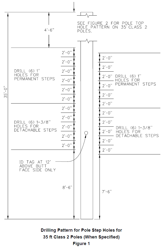
Each pole shall have two corrosion resistant ID tags securely attached as follows. On poles less than or equal to 85 feet in length the center of the first tag shall be located exactly 12 feet from the butt of the pole, oriented at 90° from the step holes. On poles greater than or equal to 90 feet in length the center of the first tag shall be located exactly 15 feet from the butt of the pole, oriented at 90° from the step holes. The second tag shall be attached to the bottom of the butt of the pole. Each tag shall have the manufacturer’s name or logo, catalog number, pole length, pole class, and date of manufacture (month/year) permanently embossed or stamped on it.
4.8 Section Length
Poles 50 feet and less in length shall be single piece and not more than 3 inches shorter or 6 inches longer than nominal length. Poles more than 50 feet shall be not more than 6 inches shorter or 12 inches longer than nominal length. Pole length shall be measured between the extreme ends of the pole.
4.9 Circumference
For a given length and class, the circumference of a FRP pole at the top and ground line shall vary no more than ± 35% from that of a Douglas Fir wood pole of the same length and class, as specified in ANSI O5.1.
4.10 Weight
FRP pole weights shall not exceed those listed below, unless authorized by the District.
| Cat ID | Length & Class | Max. Weight (lb) |
|---|---|---|
| 1001475 | 35 ft Class 2 | 400 |
| 1001408 | 45 ft Class 2 | 550 |
| 1001476 | 50 ft Class 1 | 625 |
| 1002944 | 50 ft Class H2 | 825 |
| 1001477 | 55 ft Class 1 | 800 |
| 1001945 | 55 ft Class H2 | 980 |
| 1002265 | 60 ft Class 1 | 925 |
| 1002282 | 60 ft Class H2 | 1050 |
| 1002449 | 65 ft Class 1 | 1100 |
| 1002450 | 65 ft Class H2 | 1200 |
| 1003473 | 70 ft Class 1 | 1225 |
| 1003678 | 70 ft Class H2 | 1300 |
| 1002894 | 75 ft Class H2 | 1500 |
| 1003005 | 80 ft Class 1 | 1225 |
| 1003006 | 80 ft Class H2 | 1800 |
| 1003007 | 85 ft Class 1 | 1400 |
| 1003008 | 85 ft Class H2 | 2000 |
| 1002988 | 90 ft Class H2 | 2275 |
5. Strength Requirements
FRP poles shall meet all strength requirements of NESC-2017 Rule 261.A.1 for any combination of vertical, transverse, and longitudinal loads for NESC, Grade B construction. For design purposes, FRP pole strengths shall be equivalent to that of wood poles meeting the requirements of ANSI O5.1-2017. Since FRP poles have a higher strength factor than wood poles, the horizontal loads in ANSI O5.1-2017 shall be reduced by the wood pole strength factor of 0.65 in NESC-2017 Table 261-1 as follows:
| Class | Horizontal Load (lb) |
|---|---|
| H6 | 7,410 |
| H5 | 6,500 |
| H4 | 5,655 |
| H3 | 4,875 |
| H2 | 4,160 |
| H1 | 3,510 |
| 1 | 2,925 |
| 2 | 2,405 |
5.1 Strength at Attachment Bolts
FRP poles shall support the simultaneous application of a 3,000 lb horizontal and 5,000 lb vertical load on a 5/8 inch through bolt reinforced with 3 inch curved washers without damage to the pole or permanent deformation of the bolt hole. Fiberglass poles shall be designed for a nominal through bolt installation torque of 50 ft-lb, but must withstand an installation torque of 100 ft-lb without damage.
5.2 Strength at Pole Steps
FRP poles shall support a sustained vertical load of 750 lb applied 6 inches away from the pole surface on a Senior Industries SI-0040 permanent pole step or a Lindsey 2402 removable pole step.
5.3 PLS-CADD Component Library
Pole manufacturers shall make available a current PLS-CADD component library for all pole lengths and classes offered to The District.
6. Drilling
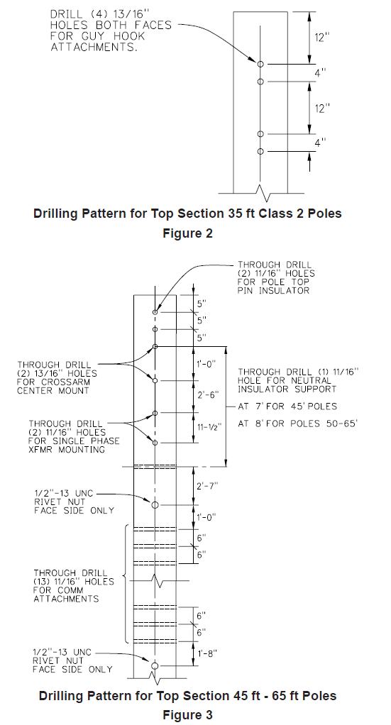
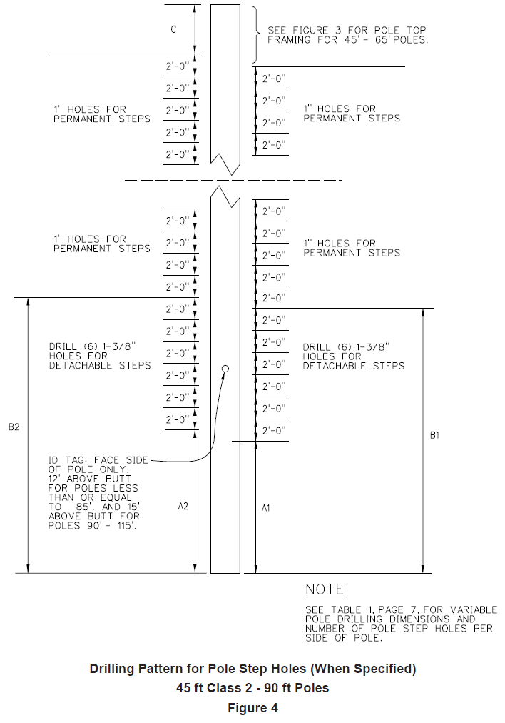
All FRP Poles shall be drilled in accordance with the the drilling details listed below. Climbing and working step holes are optional, but may be specified in the Special Provisions Sheet at the District's discretion.
| Cat ID | Length & Class | Drilling Detail | Optional Step Detail |
|---|---|---|---|
| 1001475 | 35 ft Class 2 | Figure 2 | Figure 1 |
| 1001408 | 45 ft Class 2 | Figure 3 | Figure 4 |
| 1001476 | 50 ft Class 1 | Figure 3 | Figure 4 |
| 1002944 | 50 ft Class H2 | Figure 3 | Figure 4 |
| 1001477 | 55 ft Class 1 | Figure 3 | Figure 4 |
| 1001945 | 55 ft Class H2 | Figure 3 | Figure 4 |
| 1002265 | 60 ft Class 1 | Figure 3 | Figure 4 |
| 1002282 | 60 ft Class H2 | Figure 3 | Figure 4 |
| 1002449 | 65 ft Class 1 | Figure 3 | Figure 4 |
| 1002450 | 65 ft Class H2 | Figure 3 | Figure 4 |
| 1003473 | 70 ft Class 1 | As specified by the District | Figure 4 |
| 1003678 | 70 ft Class H2 | As specified by the District | Figure 4 |
| 1002894 | 75 ft Class H2 | As specified by the District | Figure 4 |
| 1003005 | 80 ft Class 1 | As specified by the District | Figure 4 |
| 1003006 | 80 ft Class H2 | As specified by the District | Figure 4 |
| 1003007 | 85 ft Class 1 | As specified by the District | Figure 4 |
| 1003008 | 85 ft Class H2 | As specified by the District | Figure 4 |
| 1002988 | 90 ft Class H2 | As specified by the District | Figure 4 |
All holes shall be parallel with or perpendicular to each other as specified. All holes shall be clean, completely open and shall be sealed with a securely attached plug. The plugs shall be of a color that matches the pole.
| Pole Length (ft) |
Bottom of Pole to Ground line (ft) |
A1 Distance from Bottom of Pole to First Detachable Step Hole A1 (ft) |
B1 Distance from Bottom of Pole to First Permanent Step Hole B1 (ft) |
A2 Distance from Bottom of Pole to First Detachable Step Hole A2 (ft) |
B2 Distance from Bottom of Pole to First Permanent Step Hole B2 (ft) |
No. of 1-3/8" Holes for Detachable Steps on Each Side of Pole |
No. of 1" Holes for Permanent Steps on Each Side of Pole |
Distance of Highest Step Hole from Top of Pole (ft) |
|---|---|---|---|---|---|---|---|---|
| 45 | 6.5 | 8.5 | 20.5 | 9.5 | 21.5 | 6 | 11 | 3.5 |
| 50 | 7.0 | 9.2 | 21.0 | 10.0 | 22.0 | 6 | 13 | 4.0 |
| 55 | 7.5 | 9.5 | 21.5 | 10.5 | 22.5 | 6 | 15 | 4.5 |
| 60 | 8.0 | 10.0 | 22.0 | 11.0 | 23.0 | 6 | 17 | 5.0 |
| 65 | 8.5 | 10.5 | 22.5 | 11.5 | 23.5 | 6 | 20 | 3.5 |
| 70 | 9.0 | 11.0 | 23.0 | 12.0 | 24.0 | 6 | 22 | 4.0 |
| 75 | 9.5 | 11.5 | 23.5 | 12.5 | 24.5 | 6 | 24 | 4.5 |
| 80 | 10.0 | 12.0 | 24.0 | 13.0 | 25.0 | 6 | 26 | 5.0 |
| 85 | 10.5 | 12.5 | 24.5 | 13.5 | 25.5 | 6 | 29 | 3.5 |
| 90 | 11.0 | 13.0 | 25.0 | 14.0 | 26.0 | 6 | 31 | 4.0 |
7. Testing
Reports of all tests performed on these poles, or on poles that closely resemble those proposed, shall be submitted prior to shipping the District’s poles.
8. Packaging And Delivery
Poles shall be shipped on an open flatbed trailer in a bundle that may be handled and easily unloaded by forklift without damage to the poles. The butts and tops of each row shall be alternated. Pole bundles shall be secured by cushioned 2 inch x 4 inch support braces and banding straps. Positions of the bracing and banding shall be approximately 36 inches to 48 inches from each end, and then evenly divided along the length with no more than 15 feet between support braces. These cushioned braces shall be located in between each layer of poles at each bracing/banding strap location to prevent poles from rubbing together during shipment.
Poles damaged in shipment, not drilled correctly, or otherwise not meeting this specification will be rejected, and the cost of returning the poles to the vendor shall be at the vendor’s expense.
9. Bidders' Data
Prior to shipping, each bidder shall submit an outline drawing of pole(s) including all dimensions. A description of any proposed changes, additions, or exceptions to the Standard, shall be submitted along with reasons for the departure.
10. Evaluation of Bids
The following factors will be considered in the analysis and evaluation of bids and subsequent bid award:
- Adherence to standard
- Quality of product
- Past performance of product and bidder
- Proposed delivery
- Per unit bid price