Revision 0
Jun 14, 2012
937774.1 115kV Polymer Vertical Post Insulators w-o Bracket
Click here for a PDF of this Material Standard
1. Scope
This specification applies to the District's requirements for composite, non-ceramic, polymeric vertical post insulators for conductors on a 115kV electrical transmission system. The polymeric covering, including the weathersheds, shall be made of silicone rubber.
2. Reference Standards
Insulators shall meet the applicable requirements of the latest revisions of the following standards.
| Industry Standards | |
| ANSI C29.7-2002 | Wet Process Porcelain Insulators - High Voltage Line - Post Type |
| ANSI C29.17-2002 | Insulators - Composite Line Post Type |
| ASTM-153-09 | Standard Specification for Zinc Coating (Hot-Dip) on Iron and Steel Hardware |
| District Standards | |
| Compatible Unit I0703 | 115kV Polymer Vertical Post Insulator w/ o Bracket |
3. Material ID Number
This specification applies to the following District Material ID number: 937774.
4. Ratings
| Physical Specifications | |
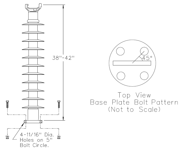
| Length (Conductor to Pole) | 38" min - 42" max |
| Core Diameter | 2.5" min |
| Color | Sky Gray, ANSI 70 |
| Minimum Mechanical Specifications | |
| Design Cantilever Load (DCL) | 1500 lb |
| Minimum Electrical Specifications | |
| Arcing Distance | 30" |
| Leakage Distance | 68" |
| Dry Flashover 60 Hz (kV RMS) | 290 kV |
| Wet Flashover 60 Hz (kV RMS) | 260 kV |
Upon request, manufacturers shall provide a combined loading chart for review by the District.
5. Construction
Insulator strength member shall be made of fiberglass rod. All parts of the fiberglass rod shall be completely covered with the same silicone rubber polymeric material as the weathersheds. The entire length of the polymeric covering, including the weathersheds, shall be one continuous, seamless piece of material. Weathersheds shall retain their original shape after severe deformation. Weathersheds shall shed water and be self-cleaning with rain.
6. Corona Ring
All insulators shall have the ability to be easily retrofitted with a corona ring.

7. End Fittings
Each insulator shall be equipped with a vertical trunnion adapter for attaching a conductor clamp. The adapter shall be dimensioned per ANSI C29.7, latest revision. Base shall have a flange with 4-11/16" holes on a 5" bolt circle oriented as shown in the figure above.
End fittings may be constructed from high strength aluminum alloy or malleable or ductile iron, galvanized in accordance with ASTM A153, latest revision. End-fittings shall have sealant applied to protect against moisture penetration. Insulator, flange end-fitting, and vertical adapter clamp shall be shipped assembled.
8. Identification
Each insulator shall be permanently marked with the manufacturer's name or logo and the date of manufacture. Each insulator shall be marked with the designed cantilever load rating (DCL) with appropriate units. The markings shall be legible and durable. Packages containing multiple insulators shall be marked with the manufacturer's name, the type of insulator and the insulator part number.