648058.1 Step-Voltage Regulator
Click here for a PDF of this Material Standard
Revision 8
Jan 1, 2018
1. Scope
This Material Standard covers the requirements for furnishing and delivering single-phase 60 Hz, mineral-oil-immersed, self-cooled 7620 volt regulators, suitable for use on a 12,470 Grounded Y/7200 volt grounded neutral distribution system.
2. Material ID Numbers
This Material Standard applies to District Material ID’s:
648032 for a 114 kVA unit
648058 for a 250 kVA unit
648066 for a 333 kVA unit
5000332 for a 3Ø CL7 Control Panel
5000334 for a 1Ø CL7 Control Panel
5000333 for a 60' 12-Pin Control Cable
5000320 for a 40' 12-Pin Control Cable
3. Reference Standards
The regulator supplied under this Material Standard shall conform to the characteristics, definitions, terminology and requirements of the latest editions, amendments and supplements of:
ANSI/IEEE Standard C57.12.90 IEEE Standard Test Code for Liquid-Immersed Distribution, Power, and Regulating Transformers and IEEE Guide for Short-Circuit-Testing of Distribution and Power Transformers
ANSI/IEEE Standard C57.15 IEEE Standard Requirements, Terminology, and Test Code for Step-Voltage and Induction-Voltage Regulators
ANSI/IEEE Standard C57.114 IEEE Seismic Guide for Power Transformers and Reactors
4. Electrical Ratings
4.1 Rated Voltage 7620 volts, RMS
4.2 BIL Rating 95 kV
4.3 Phase Angle Displacement 0°
4.4 The regulator shall be full capacity with the minimum continuous rating as specified at any tap position and any output voltage between 7200 volts and 7620 volts without exceeding 55°C temperature rise.
4.5 The range of regulation shall be +10 percent (raise) and –10 percent (lower) with sixteen steps above and below rated voltage. Each step shall cause the output voltage to change by 5/8 percent of the applied input voltage.
4.6 The potential transformer ratio shall be 60:1.
4.7 Frequency 60 Hz.
5. Losses
No-load and load losses shall be measured as stated in ANSI/IEEE C57.15. Excitation (no-load) losses and load losses will be evaluated based on the dollar per kilowatt values stated on the Special Provision Sheet. The purchase price will be reduced by an amount equal to the sum of the values of the no-load and load losses that exceed the guaranteed values.
6. Construction
6.1 Tank
6.1.1 The tank shall be of welded steel construction free from leaks and seepage. The surface shall be properly cleaned and painted for protection against severe atmospheric conditions, oxygen, acid salts and alkalis.
6.1.2 All external fittings, cover bolts, washers and nuts shall be stainless steel. Clamping devices shall be of corrosion resistant material.
6.1.3 The tank finish shall be ANSI #70 light gray, Munsell 5BG7.0/0.4.
6.1.4 The tank shall be furnished with lifting lugs and jack lugs for lifting the entire regulator with oil.
6.1.5 The tank shall have an oil drain valve with sampling device, and an oil level sight window indicating oil level height.
6.1.6 Two copper-faced stainless steel NEMA 2-hole grounding pads shall be located on opposite sides of the tank.
6.1.7 Surge arrester mounts shall be located by the load and source bushings.
6.2 Height
Regulator overall height shall not exceed 7’-6” and width (with panel &/or dial facing front) shall not exceed 4’-0”.
6.3 Bushings
One source, one load, and one neutral cover mounted bushing terminal suitable for either horizontal or vertical connections of #2 to 500 kcmil cable shall be provided. Clamps shall be capable of accepting either copper or aluminum conductors.
6.4 Nameplate
The nameplate shall be attached to the outside of the regulator and shall include all data required in the latest revision of C57.15. The internal PTs shall be clearly marked for load and source side. A statement shall be included that the “oil contains less than 1 ppm PCB at time of manufacture.”
6.5 Tap-Changing Mechanism
The tap-changing mechanism shall be completely immersed in oil. The tap-changer, in the manual position shall have the ability to operate from -16L to +16R in less than 10 seconds. The tap-changer shall be self-aligning, have a tap position feedback circuit and be motor driven.
7. Accessories
7.1 The regulator shall contain two sources of voltage (source and load potential transformers) for:
7.1.1 Sensing the voltage for forward and reverse directions of regulation, and
7.1.2 Power for tap changer motor and control panel functions.
The regulator shall be capable of giving the ratio of line voltage to secondary voltage of 7200:120 which is to be read at the "Voltage Test" terminals located on the control panel face.
7.2 By-pass arrester.
7.3 Operating motor.
7.4 The regulator shall include installed wildlife guards that cover the series lightning arrester and all primary bushings.
7.5 The regulator shall include installed source and load surge arresters and brackets assembled on the tank.
8. Control Panel
The Control Panel shall come equipped with the following:
8.1 The capability of having one set of values for Time Delay, Bandwidth, Voltage Level and Line Drop Compensation settings for “FORWARD FLOW” and another set of values for Time Delay, Bandwidth, Voltage Level, and Line Drop Compensation settings for “REVERSE FLOW”. The Control Panel shall automatically determine which set of values to operate with by the internally sensed line current direction.
8.2 Selector control to adjust the range of bandwidth for the regulated voltage.
8.3 Line drop compensator with self-contained current source and polarity switch.
8.4 Manual/Automatic motor control switch with positions for off, automatic, raise and lower.
8.5 Ability to automatically reverse regulation upon change of current flow with the option to inhibit reversing for current magnitudes less than 2 percent of full-rated current (or equivalent option).
8.6 Voltage testing terminals that monitor regulated voltage. The voltage on the “Voltage Test” terminals shall be the regulated voltage determined by the mode of regulation (forward or reverse regulation).
8.7 Time delay control with a setting range of 0 - 120 seconds.
8.8 Digital (True RMS), voltmeter, power-factor meter and ammeter with accuracy of one percent or less and capable of reading instantaneous values of each.
8.9 First House Protection (voltage limit over-ride controls). This First House Protection package shall have upper and lower limit controls to limit the regulated voltage. The lower limit control range shall be at least 105 to 120 volts and the upper limit shall be at least 120 to 135 volts. This accessory shall come with an “on/off” switch and indicators showing when the lower or upper limits have been activated.
8.10 A digital read-out instrument with memory for the highest voltage, lowest voltage, highest load current, lowest power factor, and highest power factor, most leading and most lagging power factor. Memory shall date-time stamp each of the previously mentioned readings. This instrument shall be installed by the manufacturer.
These memory values shall have a selectable demand period (changeable in the field under operating conditions) range of 1, 2, 5, 15, 30 and 60 minutes. These memory values shall have an accuracy of 1 percent or less from measured values.
8.11 Shall be SCADA capable with the following characteristics:
8.11.1 Outputs
Instantaneous source and load bushing voltage (true RMS).
Instantaneous load current.
Instantaneous power factor (with lead or lag indication).
Demand current, MVA and MVAR with date-time stamp.
Instantaneous MVA and MVAR.
8.11.2 Control Functions
The ability to be remotely switched from “AUTOMATIC” control to “MANUAL” control and back.
The ability to “RAISE” or “LOWER” the tap changer.
8.11.3 Status Functions
The Control Panel shall report whether it is in “MANUAL” or “AUTOMATIC” operation.
The Control Panel shall report the position of the tap changer which is also indicated by the external position indicator.
8.12 The Control Panel or the Control Panel Enclosure shall come with a quick disconnect for removal or change-out. The quick disconnect shall be secured by screw-type connection or approved equivalent.
8.13 The Control Panel shall be connected to the regulator by a 40 or 60 foot control cable. This control cable shall connect between the regulator and control panel with a canon type plug on each end.
8.14 The Control Panel shall be capable of uploading or downloading parameters and data via flash card or USB jump drive without the use of external computers or hand-held devices.
8.15 The Control Panel shall have DNP3 protocols resident in the controller and shall be user-configurable for all communication ports. The Control Panel shall be DNP3 protocol certified level 2 compliant.
8.16 The Control Panel shall be able to perform preventive maintenance tapping.
8.16.1 Shall have the ability to exercise the tap-changer, based on user defined condition, on a routine basis to prevent the build-up of carbon deposits on the contacts.
8.16.2 Shall have two modes available, allowing the various degrees of configurability and the ability to exercise all stationary and movable contacts.
8.17 The Control Panel shall have a duty cycle monitor that will calculate the life used for all contacts of the tap changer based upon actual service condition and individual regulator design.
8.18 The controller shall have a time on tap feature that provides specific information about the amount of time that the regulator has spent on each tap position.
9. Oil
The regulator shall be shipped with the proper quantity of mineral insulating oil. Oil shall meet the requirements of ASTM D 3487 for Type II (inhibited) oil. At the time the oil is put into the tank it shall contain less than (1) ppm PCB certifiable by a laboratory test approved by the United States Environmental Protection Agency. The insulating oil, or any of its components, shall not be listed by IARC, NTP, OSHA or ACGIH as carcinogens. The successful bidder shall supply an MSDS sheet for each distinct formulation of insulating oil supplied to the District.
10. Non PCB Decal
10.1 A “NON PCB” decal shall be attached to each regulator. “NON-PCB” decals shall conform to the latest revision of District Material Standard 1000212.1.
10.2 The decal shall be positioned on the bottom half of the regulator tank, aligned with the centerline of either the 2nd or 4th quadrants.
11. Spare Parts
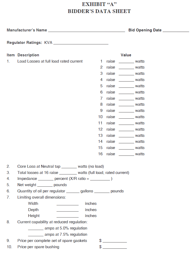
The price per complete set of spare gaskets and per spare bushing, which may be purchased at the option of the DISTRICT, shall be furnished in Exhibit A.
12. Drawings and Diagrams
A minimum of 30 days before the date of delivery, the supplier shall furnish three copies of each of the following, certified correct and approved for installation:
12.1 Outline drawing of the regulator, showing dimensions and locations of all accessories.
12.2 Drawing of the nameplate.
12.3 Control wiring diagram.
12.4 An Installation - Operation - Maintenance manual.
12.5 Control panel wiring diagrams.
One copy of each shall be supplied and shipped within each control panel door of each regulator.
13. Test Reports
The supplier shall furnish four certified copies of the test report on each regulator. These tests shall be a minimum of the routine tests described in ANSI C57.15, latest revision. Mail reports to:
PUD No. 1 of Snohomish County
Attention: System Planning & Protection O1
P.O. Box 1107
Everett, WA 98206-1107
14. Bidder's Data
For each rating of regulator, each BIDDER shall submit with their proposal complete data and information as requested in Exhibit “A” of this Material Standard. A description of any proposed changes, additions or exceptions to this Material Standard shall be submitted along with the reasons for the departure.
BIDDER shall also submit:
14.1 Pole or platform mounting details.
14.2 Photograph of the complete control panel with an attached list itemizing the standard accessories in the control panel package.
14.3 Detailed description by supplier of the manufacturer’s control panel exchange program (if available). This should include dollar values for exchange of identical panels (for repair purposes) as well as exchange of older panels (for upgrading purposes) to present technology.
15. Evaluation of Bids
The following factors will be considered in the analysis and evaluation of bids and subsequent bid award.
15.1 Proposed delivery.
15.2 Past performance of BIDDER and product.
15.3 Conditions of warranty.
15.4 Completeness of BIDDER’s data.
15.5 Initial cost and escalations.
15.6 Load and excitation losses.
15.7 Load losses at 100 percent on each tap (even and odd).
15.8 Construction details.
16. Penalties
16.1 The manufacturer will be assessed a penalty for regulators delivered that exceed the guaranteed loss values stated on the bid proposal. The penalty shall be the amount the loss is higher than the loss values guaranteed in the proposal.
16.1.1 Excitation Loss Penalty = Excess Excitation Loss X Excitation Loss value shown on the Special Provision sheet.
16.1.2 Load Loss Penalty = Excess Load Loss X Excess Load Loss value shown on the Special Provision sheet.
16.2 Tolerance will be allowed in accordance ANSI C57.15-1986, Section 5.7.2 Table 9. However, the tolerance allowance has no effect on the penalty calculation.
16.3 After delivery, all of the delivered lot will be inspected for defects and conformance to this Material Standard and tested for proper internal connections. The manufacturer (or his representative) will be notified of all defects and mutual arrangements shall be made for correcting the defects at no expense to the DISTRICT. All subsequent testing required due to defects will be at the manufacturer’s expense.
17. Warranty
17.1 The successful BIDDER shall guarantee all parts of the regulator against defects in material and workmanship for a minimum of 12 months from date of energization or 18 months from the shipping date, whichever comes first.
17.2 Upon written notice from the DISTRICT, the successful BIDDER shall immediately repair or replace, at his own expense, all or any part of the regulator that may prove to be defective during the period of this guarantee, whether installed initially or installed as repair or replacement under this guarantee.
17.3 The successful BIDDER further guarantees that the warranty for repaired or replaced material shall be of an equal duration as the original warranty period and shall start upon acceptance of such repaired or replaced material.
18. Delivery
The successful BIDDER shall deliver the regulators by the date shown on the Special Provision Sheet. BIDDER will give notice to the DISTRICT in writing when a change in delivery is anticipated. If at any time the DISTRICT has reasonable cause to believe that delivery will not be made at the time and place specified, the DISTRICT shall have the right to terminate the Purchase Order, but shall not be obligated to do so.
19. Rights For Damages
Nothing in this Material Standard shall impair any rights for damages which the DISTRICT might otherwise have by reason of the failure of the BIDDER to deliver in accordance with contract documents.
20. Shipment
20.1 Shipment shall be:
F.O.B. PUD No. 1 of Snohomish County
Operations Center Receiving
1802 75th Street SW
Everett, WA 98203-6264
20.2 Eequipment damaged in shipment will be refused on delivery and it will be the BIDDER’s responsibility to arrange the prompt repair or replacement to the standards of new equipment. The BIDDER will not be relieved of the responsibility of delivering undamaged equipment, even if the damage is internal, or otherwise goes undetected and the nature of the damage remains unknown until the equipment is energized and tested.
20.3 Equipment shall be suitably packed to ensure against damage from weather or transportation, in accordance with the requirements of common carriers.
20.4 BIDDER shall be responsible for checking the shipping dimensions and weight of the proposed design for compatibility for railroad or truck shipment.
20.5 Two weeks prior to delivery the BIDDER shall notify the DISTRICT in writing of the shipment delivery date.
Notice shall be sent to:
PUD No. 1 of Snohomish County
Attention: System Planning & Protection O1
P.O. Box 1107
Everett, WA 98206-1107
21. Service and Repair Capability
Expedient repair of regulators is necessary for the efficient and economic operation of DISTRICT facilities. The DISTRICT will only purchase regulators from BIDDERS who have documented, to the satisfaction of the DISTRICT, that service, repair, and spare parts facilities are available.
22. Payment
Upon certification by the DISTRICT that all material has been received in satisfactory condition and in accordance with this Material Standard, payment in full for each unit will be made.
23. General Bidding Conditions
The attached General Bidding Conditions are made a part of this Material Standard.