647076.2 3Ø Pole-Mnt SCADA Comp Microprocessor-Based Solid Dielectric Line Recloser
Click here for a PDF of this Material Standard
Revision 0
Jun 28, 2005
1. Scope
This Specification covers the requirements for furnishing and delivering a three-phase 60 Hz, outdoor, pole-mounted SCADA compatible microprocessor-based line recloser. The interrupting medium shall be axial-magnetic field vacuum.
2. Material ID Number
This Specification applies to District Material ID Number 1001790.
3. Reference Standards
The recloser supplied under this Specification shall conform to the characteristics, definitions, terminology, and requirements of the latest editions, amendments and supplements of:
ANSI/IEEE Standard C37.60 IEEE Standard Requirements for Overhead, Pad-Mounted, Dry Vault and Submersible Automatic Circuit Reclosers and Fault Interrupters for AC Systems
ANSI/IEEE Standard C37.61 IEEE Standard Guide for the Application, Operation and Maintenance of Automatic Circuit Reclosers
4. Electrical Ratings
| Nominal Voltage | 14.4kV |
| Maximum Voltage | 15.5kV |
| BIL | 110kV |
| Power Frequency | 60 Hz |
| Continuous Current Rating | 630 amps |
| Interrupting Current | 12500 amps (Symmetrical) |
5. Construction
5.1 Tank
5.1.1 The tank shall be of welded steel construction free from leaks and seepage. The surface shall be properly cleaned and painted for protection against severe atmospheric conditions, oxygen, acid, salts and alkalis.
5.1.2 All external fittings and cover bolts, washers and nuts shall be stainless steel. Clamping devices shall be of corrosion resistant material.
5.1.3 The tank finish shall be ANSI Z55.1, light gray No. 70, Munsell 5.0 BG 7.0/0.4.
5.1.4 The tank mounting bracket shall not have braces extending over the top of the tank. The pole mounting bracket surfaces shall be processed in accordance with 5.1.1.
5.2 Bushings
Three source and three load bushings of cycloaliphatic epoxy shall be provided. Clamp type terminals suitable for either horizontal or vertical connection of #2 AWG to 500 kcmil stranded copper conductor shall be provided.
5.3 Nameplate
The nameplate shall be attached to the outside of the recloser and shall include all data required in ANSI C37.60.
5.4 Control Panel Enclosure
The control panel enclosure shall incorporate the following features:
5.4.1 The control panel enclosure shall be weatherproof. The surface shall be processed as described in 5.1.1.
5.4.2 The control panel enclosure shall be equipped with two mounting brackets; one shall be above and the other below the enclosure. These two brackets shall be constructed to stand the panel off from the pole at least 6 inches. The brackets shall be able to accommodate galvanized bolts mounted through the pole.
5.4.3 All connectors and control cables shall mount to the bottom side of the control panel enclosure. The connectors shall be weatherproof and shall be a quick disconnect type that do not require tools for makeup or removal; i.e., they shall be screwed cannon plug type or equivalent.
5.4.4 The control panel enclosure shall be equipped with a drip gutter to prevent the ingress of water when the control panel enclosure door is open in wet weather.
5.4.5 The control panel enclosure shall be equipped with a handle that is capable of being locked with the District's padlocks, both long and short shanks.
5.4.6 The control panel enclosure shall include a lug for panel grounding.
5.4.7 The control panel enclosure shall include an 8 Amp-Hour 24 volt DC lead acid battery for operation upon loss of AC power. The battery shall be capable of maintaining full operation for a 15 hour maximum period at 20 °C.
5.4.8 The control panel enclosure shall include a heavy duty terminal block with #6-32 AWG screw terminal positions for terminating the District's wiring from the RTU. An easily readable, permanent method shall be used to identify all external connection terminal blocks.
6. Recloser Switch
The recloser switch shall be equipped with or feature the following:
6.1 Self-contained bushing type current transformers or equivalent for sensing instantaneous values of load current and fault current
6.2 Lifting lugs for lifting the entire recloser
6.3 Lugs for tank grounding
6.4 Current interruption shall occur in vacuum interrupters, providing long contact life while eliminating the production of toxic by-products.
6.5 Surge arrester mounts located by each load and source bushing
6.6 A yellow-coated manual operating handle for manual lockout - This handle shall be easily seen from the ground.
6.7 Overall height shall not exceed 37 inches and width shall not exceed 21 inches
6.8 An indicator showing the position of the contacts within the recloser - This indicator shall be easily seen from the ground. When contacts are in the open position, the indicator will show an "OPEN" indication, and when the contacts are in the closed position, the indicator will show a "CLOSED" indication.
6.9 A 'Closing Tool Port' or the equivalent to manually close the recloser when in the shop being tested
6.10 Bird guards that cover the top skirt and clamp terminal of each bushing
6.11 A contact position semaphore shall be mounted on the bottom of the recloser for access viewing from 360 degrees.
6.12 The NOVA Recloser shall be capable of operation with Cooper Power Systems three-phase recloser controls, types F4C and F6.
7. Environmental
7.1 The solid dielectric insulation shall contain no environmentally hazardous or toxic components.
7.2 SF6 gas or foam is not acceptable for insulation medium.
7.3 SF6 gas is not acceptable for an interrupting medium.
8. Control Panel
The control panel shall include the following:
8.1 A selector switch or the equivalent for each of the following:
- The number of fast ground trips
- The number of fast phase trips
- The number of total trips to lockout
8.2 Selector switches or their equivalent for at least three reclosing intervals:
8.2.1 The first reclose interval shall be the time measured from the first recloser "opening" to the first recloser "reclose".
8.2.2 The second reclose interval shall be the time measured from the second recloser "opening" to the second recloser "reclose".
8.2.3 The third reclose interval shall be the time measured from the third recloser "opening" to the third recloser "reclose".
The reclose intervals shall have multiple settings between 0.3 and 1000 seconds. A reset selector switch or its equivalent shall be provided and have multiple settings of 3 to 1800 seconds. The reset time shall be the time from the last successful reclose to the recloser control re-initializing.
8.3 Selectable Time Current Curves (TCCs) - The selection of the TCCs shall be performed within the control panel without having to remove any bolts or handhole covers on the recloser switch. The TCCs shall have the ability to be modified using time multipliers and adders. The family of TCCs available must represent utility standard TCCs and coordinate with the District's "T" link and "E" link fuses.
8.4 An operational counter counting the number of trips (opens) of the recloser switch
8.5 The capability to set phase, negative sequence and ground overcurrent elements. Phase and negative sequence minimum trip range is 10 to 1600 amps. Ground minimum trip range is 5 to 800 amps.
8.6 A push button switch for manually opening or closing the recloser switch. This switch shall be equipped with LED indicators to show an open or closed condition. Internal logic will be available to block tripping for cold load and instantaneous settings during manual closing.
8.7 One-touch function keys for the following functions:
- Normal Reclosing / Non-Reclosing
- Ground Trip Block / Normal Ground Tripping
- Supervisory OFF
- Alternate Profile #1
- Alternate Profile #2
- Alternate Profile #3
- Option #1
- Option #2
- Option #3
8.8 The capability to perform sequence of events time-stamping for up to 25 event types - The panel shall be able to record oscillography that provides current and voltage waveforms along with protection element and recloser response status changes.
8.9 Eight configurable outputs for a District supplied RTU - Each status contact will be configurable to combine status functionality along with Boolean algebra. Minimum contact rating shall be 12-48 volt DC, 1 amp resistive. All contacts shall be latching.
8.10 The ability to receive eight configurable external control input contact closures from a District supplied RTU - The signal level generated by the control panel shall not exceed 1 amp at 48 volt DC.
8.11 Electrical controls for remote or local electrical operation
8.12 The ability to operate normally from 120 volt power to close the recloser switch and be equipped to prevent closing of the switch if the 120 volt power is absent
8.13 The ability to prevent reclosing if the fault current magnitude is above certain programmable levels for both ground and phase
8.14 An LED type target board which has the option of resetting the targets manually or automatically (auto reset at the presence of load current)
8.15 A space heater suitable for operation at 120 volts
8.16 A fused convenience receptacle (3-wire) mounted within the control panel enclosure
9. Cables
9.1 Control Cable
9.1.1 The control cable or any other cable between the recloser switch and the control panel shall be 24 feet in length.
9.1.2 The control cable or any other cable shall have manufacturer installed terminations on both cable ends. These terminations shall be the screwed, cannon plug type or the aircraft type connector. The control cable terminations shall be polarized so the male termination connects to the recloser and the female termination connects to the control panel.
9.1.3 The control cable shall be a multicolored cable properly jacketed for protection against severe atmospheric conditions, oxygen, acid, salts and alkalis.
9.2 Power Cable
9.2.1 If a power cable is required for a battery charger, low voltage closing, or voltage inputs for accessories, the cable shall be a minimum of 16 feet in length.
9.2.2 The power cable shall come with a manufacturer installed termination on one cable end and the other cable end will have no termination. (The District will use the end without termination to connect to the incoming AC power). The cable termination shall either be a screwed cannon plug type or an aircraft type connector.
9.2.3 The power cable shall be a multi-conductored cable properly jacketed for protection against severe atmospheric conditions, oxygen, acid, salts and alkalis.
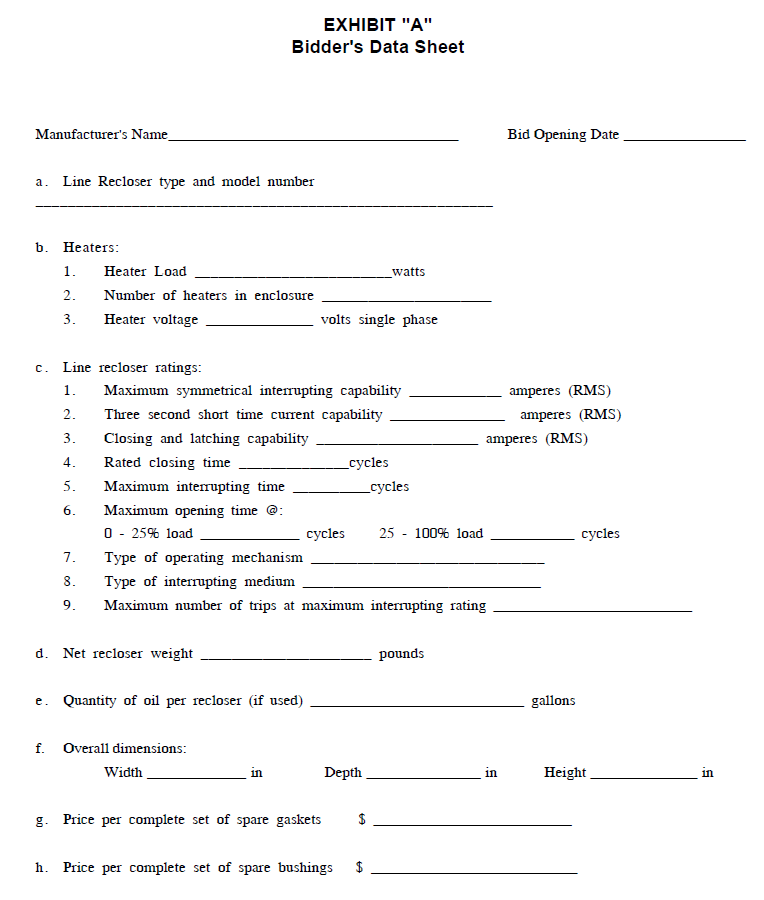
10. Spare Parts
The price per complete set of spare gaskets and per complete set of spare bushings, which may be purchased at the option of the District, shall be furnished in Exhibit A.
11. Auxiliary and Control Power
11.1 The recloser mechanism shall be suitable for operation at 120 volt, single-phase, 60 Hz. The recloser trip mechanism shall be rated for operation at 24 volt DC (±2 volts).
11.2 Three-wire, 120 volt, single-phase, 60 Hz AC power supply shall be made available by the District for the space heater and other control panel and recloser switch accessories.
12. Drawings and Diagrams
A minimum of 30 days before the date of delivery, the supplier shall furnish three copies each of the certified correct and approved for installation drawings as follows. One copy of each of these drawings shall also be supplied and shipped within the control panel door of each recloser.
- Outline drawing of the recloser, showing dimensions and locations of all accessories
- Drawing of the nameplate
- Control schematic and wiring diagram
- Installation - Operation - Maintenance manual
- Control panel schematic drawing including all add-on accessories which were required to meet this specification
13. Test Reports
The supplier shall furnish one certified copy of the test reports for each recloser. These tests shall be a minimum of the routine tests described in ANSI C37.60.
14. Service and Repair Capability
Because the expedited repair of line reclosers is necessary for the efficient and economic operation of District facilities, the District will only purchase line reclosers from bidders who have documented, to the satisfaction of the District, that service, repair and spare parts facilities are readily available.
15. Bidders' Data
15.1 For each rating of recloser, each bidder shall submit with their proposal complete data and information as requested on Exhibit "A" of this specification. A description of any proposed changes, additions or exceptions to the Specification shall be submitted along with reasons for the departure.
15.2 Bidder shall also submit:
15.2.1 Pole mounting details
15.2.2 Drawings of the complete control panel with an attached list itemizing the accessories in the control panel package
15.2.3 A detailed description of manufacturer's control panel exchange program - This should include dollar values for exchange of identical panels for repair purposes.
16. Evaluation of Bids
The following factors will be considered in the analysis and evaluation of bids and subsequent bid award:
16.1 Proposed delivery
16.2 Past performance of bidder and product
16.3 Conditions of warranty
16.4 Completeness of bidder's data
16.5 Construction details
16.6 Manufacturer's control panel exchange program
17. Warranty
17.1 The successful bidder shall guarantee all parts of the line recloser against defects in material and workmanship for a minimum of 12 months from date of energization or 18 months from the shipping date, whichever comes first.
17.2 Upon written notice from the District, the successful bidder shall immediately repair or replace, at the bidder's own expense, all or any part of the line recloser that may prove to be defective during the period of this guarantee, whether installed initially or installed as repair or replacement under this guarantee.
17.3 The successful bidder further guarantees that the warranty for repaired or replaced material shall be of an equal duration as the original warranty period and shall start upon acceptance of such repaired or replaced material.
18. Delivery
The successful bidder shall deliver the line recloser(s) by the date shown on the Special Provision Sheet. Bidder will give notice to the District in writing when a change in delivery is anticipated. If at any time the District has reasonable cause to believe that delivery will not be made at the time and place specified, the District shall have the right to terminate the Purchase Order, but shall not be obligated to do so.
19. Shipment
19.1 Shipment shall be:
FOB Public Utility District No. 1 of Snohomish County
Operations Center Receiving
1802 75th Street SW
Everett, WA 98203-6264
19.2 Equipment damaged in shipment will be refused on delivery and it will be the bidder's responsibility to arrange for prompt repair or replacement to the standards of new equipment. The bidder will not be relieved of the responsibility of delivering undamaged equipment, even if the damage is internal, or otherwise goes undetected and the nature of the damage remains unknown until the equipment is energized and tested.
19.3 The line recloser(s) shall be suitably packed to ensure against damage from weather or transportation, and in accordance with the requirements of common carriers.
19.4 Bidder shall be responsible for checking the shipping dimensions and weight of the proposed design for compatibility for railroad or truck shipment.
19.5 Two weeks prior to delivery the bidder shall notify the District in writing of the line recloser(s) delivery date.
Notice shall be sent to:
Public Utility District No. 1 of Snohomish County
Attention: System Planning & Protection O1
PO Box 1107
Everett, WA 98206-1107
20. Inspection
After delivery, inspection shall be in accordance with Section 2 of the District's Purchase Order Terms and Conditions, latest revision. If returning rejected equipment to the supplier, the shipping costs will be at the supplier's expense.
21. Correction of Deficiencies and Nonconformities
Any opportunity for the Supplier to correct deficiencies and nonconformities will be at the sole discretion of the District and at the sole expense of the Supplier. If the District elects to allow corrections, mutual arrangements shall be made for their completion. Any subsequent testing required due to deficiencies and nonconformities will be at the Supplier's expense. All shipping costs associated with correction of deficiencies and nonconformities will be at the Supplier's expense.
22. General Bidding Conditions
The attached General Bidding Conditions are made a part of this Specification.