Revision 3
Oct 26, 2021
506751.1 115kV 1200A Group Operated Unitized Vertical Break Switch
Click here for a PDF of this Material Standard
1. Scope
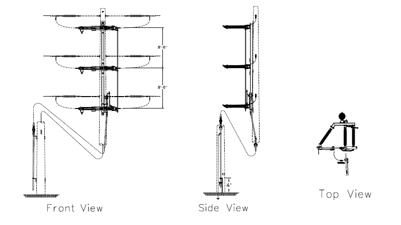
This Specification covers the requirements for furnishing and delivering 115kV 1200A group operated unitized, vertical break phase-over-phase slant "V" insulator configuration switches.
2. Reference Standards
All characteristics, definitions, terminology, voltage designations and tests, except as otherwise specified herein, shall be in accordance with the following industry and District standards. When the following standards are superseded by an approved revision, the revision shall apply.
Industry Standards
| ANSI C37.30.1 - 2011 | IEEE Standard Requirements for AC High-Voltage Switches Rated Above 1000 V |
| ANSI C37.32 - 2002 | American National Standard for High Voltage Switches, Bus Supports, and Accessories Schedules of Preferred Ratings, Construction Guidelines, and Specifications |
| ANSI C37.34 - 1994 | IEEE Standard Test Code for High-Voltage Air Switches |
| ANSI C37.37 - 1996 | IEEE Loading Guide for AC High-Voltage Air Switches (in Excess of 1000 V) |
| IEEE 1247 - 2005 | IEEE Standard for Interrupter Switches for Alternating Current, Rated Above 1000 V |
| ASTM A123 - 13 | Standard Specification for Zinc (Hot-Dip Galvanized) Coatings on Iron and Steel Products |
District Standards
| Compatible Unit D0801 | Switch 115kV 1200A 3Ø Group-Operated Unitized Manual Operator - 1-Pole Vertical Mounting |
| Assembly Unit 115V703 | 115kV Manually Operated Unitized Switch |
3. General
115kV 1200A group operated unitized switches shall be factory assembled and designed for vertical mounting on round wood, laminated wood, fiberglass and steel transmission poles. All three switch mechanisms shall be unitized on a single mounting frame and factory adjusted for proper alignment and synchronized opening or closing.
4. Material ID Number
| Material ID | Description |
|---|---|
| 506751 | Switch, 115kV 1200A Group Operated Unitized Vertical Break Switch |
| 5000063 | Add-on Or Replacement Vacuum Interrupter, 115kV 1200A |
5. Ratings
The switchgear shall have the following ratings:
| Power Frequency. | 60 Hz |
| Nominal Voltage. | 115kV |
| BIL | 550 kV |
| Allowable Continuous Current. | 1,200 A |
| Short Time Withstand | 61 kA |
| ACCC Class | D06 |
| Interrupter | |
| High Velocity Whip, Line Charging or Unloaded Transformer Amps | 10 A |
| Single-Bottle Vacuum Interrupter, Loop or Parallel Switching. | 2000A if PRV <= 30kV |
| Multi-Bottle Vacuum Interrupter | 1,200 A |
| Maximum Weight | 2,700 lb |
At the District's request, the manufacturer shall furnish certified tests establishing the electrical ratings of the switch.
6. Components
6.1 Switches
Switches shall be vertical break slant style. Each switch unit shall be unitized and factory adjusted for phase over phase vertical single pole installation. Nominal phase spacing shall be 8'-6" between switches. Unitized switch assembly shall include provisions for balanced overhead lifting.
6.2 Frame
Unitizing mounting member shall be hot-dip galvanized structural steel tube or channel of sufficient size and rigidity to ensure proper switch alignment and operation throughout the expected life of the switch. Unitizing members fabricated from pipe are not acceptable. Frame shall be drilled for a minimum of 4-7/8" mounting bolts.
Upper and lower mounting bolt locations shall be keyhole slotted. All mounting holes shall be fully accessible without obstructions.
6.3 Insulators
Switch mounting insulators shall be station post silicone polymer.
6.4 Contacts
Jaw contacts shall be self-wiping, silver-to-silver, reverse loop shoe type. All other exposed current carrying contacts shall be silver-to-silver. Blade contacts shall be designed to gradually apply pressure as the switch fully closes.
6.5 Current Path
Laminated shunts, braids, contact finger springs, mechanical linkages and hinge pivot pins in the current path are not acceptable.
6.6 Bearings
The main bearing assembly which supports the rotating insulator shall consist of stainless steel ball bearings mounted in stainless steel races. Bearings shall be lubricated and sealed and shall be maintenance free for the life of the switch.
6.7 Terminal Pads
Switch terminal pads shall be NEMA standard 4-hole, suitable for aluminum, copper or bronze fittings. Terminal pads shall be oriented 90° to axis of the insulator.
7. Operating Mechanism
7.1 Switch Operation
Operation of the switch blades shall be under positive control at all times and shall travel from the fully closed to the fully open position in one smooth continuous motion. Adjustable stops in both the open and closed positions shall be provided.
7.2 Swing Handle Operator
The switch operator shall be a swing handle with a maximum operating force of 50 lb. The operating handle shall have position indicators and provisions for locking in the open and closed positions.
7.3 Control Pipe and Accessories
Switch shall utilize 2" NPS galvanized steel control pipe. Each switch assembly shall include 70 feet of control pipe along with all required couplings, guide bearings and outboard bearings. Each switch must accommodate mounting within 90° on either side of the switch position.
7.4 Control Rod Insulator
Each switch shall include one control rod insulator.
7.5 Control Rod Grounding Strap
Each switch shall include a tinned copper braid grounding strap, tinned ground connector and pipe clamp.
8. Interrupters
8.1 High Velocity Whip
Unless otherwise specified at time of purchase, switches will be equipped with high velocity whip interrupters capable of interrupting 10 amps of line charging or unloaded transformer current.
8.2 Vacuum Interrupters
When specified, switches shall be equipped with single or multi-bottle vacuum interrupters. Acceptable interrupter dielectrics shall be oil or small bubble foam. SF6 gas is not an acceptable dielectric.
8.3 Single-Bottle Vacuum
If specified at time of purchase, switches will be equipped with single-bottle vacuum interrupters rated to interrupt parallel or loop splitting up to 2,000 amps if peak recovery voltage does not exceed 35kV.
8.4 Multi-Bottle Vacuum
If specified at time of purchase, switches will be equipped with multi-bottle vacuum interrupters rated to break line current up to 1200 amps.
8.5 Interchangeability
Switches shall be capable of retrofitting to accept whip, single-bottle or multi-bottle vacuum interrupters.
9. Packaging
Each switch assembly, complete with switch, mounting hardware, operating rods and mechanism and instructions for installation, operation and maintenance of the switch shall be shipped in one crate and must have provisions for lifting with a forklift.
10. Nameplate
A corrosion-resistant nameplate shall be provided which conforms with Section 7.6 of ANSI C37.30.1.
11. Drawings and Installation Manuals
Each switch shall be packaged with one instruction manual and complete set of approval drawings in a weatherproof container. In addition, the switch manufacturer shall supply electronic copies and three hard copy sets of instruction manuals and approval drawings with each switch order.
12. Warranty
The manufacturer shall warrant all components of each switch against defects in design, material and/or workmanship for a minimum of 5 years.