1002410.1 15kV Air-Insulated Dead-Front Pad-Mounted Switchgear
Click here for a PDF of this Material Standard
Revision 6
May 22, 2020
1. Scope
This Specification covers the requirements for furnishing and delivering free-standing, self-contained, cabinet enclosed 15kV air-insulated dead-front pad-mounted switchgear with 600 amp 3Ø group-operated interrupter switches and 3Ø sets of 200 amp single-pole fuse ways configured as shown in Figure 1 or as specified in the District's Special Provisions sheet. Switchgear shall be rated for use on a 60 Hz, 12.47 Grounded Y/7.2kV electrical distribution system.
2. Reference Standards
All characteristics, definitions, terminology, voltage designations and tests, except as otherwise specified herein, shall be in accordance with the following industry standards for distribution, power and regulating transformers. When the following standards are superseded by an approved revision, the revision shall apply.
Industry Standards
ANSI C37.74-2003 IEEE Standard Requirements for Subsurface, Vault and Pad-Mounted Load-Interrupter Switchgear and Fused Load-Interrupter Switchgear for Alternating Current Systems up to 38kV
ANSI C57.12.28-2005 IEEE Standard for Pad-Mounted Equipment — Enclosure Integrity
IEEE 386-2006 IEEE Standard for Separable Insulated Connector Systems for Power Distribution Systems Above 600V
NEMA 260-1996 (R2004) Safety Labels for Pad-Mounted Switchgear and Transformers Sited in Public Areas
District Standards
Material Standard 386202.1 2-1/4" Labels for Marking District Owned Equipment
Material Standard 890526.1 Padmount Equipment Danger Label
Material Standard 890534.1 Padmount Equipment Warning Label
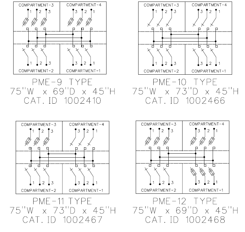
3. Connection Diagrams and Material ID Numbers
4. Ratings
The switchgear shall have the following ratings:
| Power Frequency | 60 Hz |
| Nominal Voltage | 14.4kV |
| Maximum Voltage | 17kV |
| BIL | 95kV |
| Main Bus Continuous Current | 600A |
Three-Pole Interrupter Switches
| Continuous Current | 600A |
| Load Dropping Current | 600A |
Short Circuit Current
| One-Second Short Time Withstand, RMS Symmetrical | 25,000A |
| Peak Withstand, Peak | 65,000A |
Three-Time Duty-Cycle Fault-Closing
| RMS, Symmetrical | 25,000A |
| Peak | 65,000A |
Fuses (S&C Type SMU-20)
| Continuous Current (Fuse) | 200A |
| Load Dropping Current (Fuse) | 200A |
| Short Circuit Current, RMS Asymmetrical | 22,400A |
| 3-Phase Symmetrical Load at Rated Voltage | 350 MVA |
At the District's request, the manufacture shall furnish certified tests establishing the electrical ratings of the switchgear, including ratings of the basic switches and fuse components.
5. Enclosure
5.1 General
The switchgear cabinet shall be of unitized construction (not structural frame and bolted sheet). All medium-voltage switch and fuse components shall be completely encased in an inner grounded steel compartment. The switchgear shall meet or exceed the tamper resistance requirements of ANSI C57.12.28, latest revision.
5.2 Material
The cabinet, including doors, shall be fabricated from minimum 11 gauge steel sheet. All structural joints and butt joints shall be welded and the external seams shall be ground flush and smooth.
5.3 Limiting Overall Dimensions
Nominal padmounted switch dimensions are shown in Figure 1. Minor variations may be acceptable with prior District approval.
5.4 Roof
The cabinet roof shall be constructed so as to shed water. If two roofs are used, water shall not collect at their intersection.
A heavy coat on insulating "no-drip" compound shall be applied to the inside roof surface to reduce condensation.
5.5 Base
The cabinet base shall be square and smooth and shall consist of continuous 90° flanges, turned inward and welded at the corners for bolting to a concrete pad. Flange width shall be 1" minimum, 2" maximum.
5.6 Doors
Doors shall be bulkhead type, side-hinged to swing open horizontally. Top-hinged, clam shell type doors are unacceptable. Doors shall have a minimum of 3 tamper-proof stainless hinges.
Door edge flanges shall overlap with door opening flanges so as to guard against water entry or insertion of foreign objects.
Each pair of double doors shall consist of one active and one passive door. The active door shall include a three-point latching mechanism with recessed penta head bolt and padlock hasp that requires the doors to be latched before the padlock can be inserted. The passive door shall be independently secured and latched to the enclosure.
The padlock hasp shall include a hood that protects the padlock shackle and from tampering and prevents access to the operating bolt. The hood shall be configured so it cannot be padlocked independent of the hasp.
Each door shall be provided with a stainless steel door holder located above the door opening. These holder shall be hidden from view when the door is closed. It shall not be possible for the door-holders to swing inside the enclosure. The door-holders shall hold the door open at an angle of at least 100° and at most 120°.
5.7 Base Spacer
As an optional feature the manufacture shall offer a 6, 12, 18 and 24 inch tall non-compartmented steel base spacer. The District may specify this option to be included as part of the switch or ordered separately for retrofitting.
5.8 Lifting Tabs
Factory installed removable lifting tabs shall be provided. A resilient material shall be placed between the lifting tabs and the enclosure to prevent damaging the enclosure finish. This material shall be non-hydroscopic to prevent moisture from being absorbed and retained between the tabs and enclosure in the event that the lifting tabs are not removed.
5.9 Finish
The switch shall have a corrosion resistant finish that meets or exceeds the coating system requirements of ANSI C57.12.28-2005. The topcoat color of paint shall be semi-gloss Munsell Number 7GY 3.29/1.5, pad-mount green. All finish components shall be lead free.
6. SWITCH COMPARTMENTS
6.1 Switch Terminals
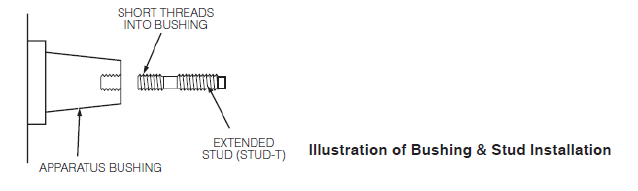
Switch terminals shall be equipped with 600A rated apparatus bushings with removable extended threaded studs in accordance with ANSI/IEEE Standard 386. The shorter threaded end of the extended stud shall be threaded into the 600A apparatus bushing as illustrated below. Parking stands shall be provided adjacent to each bushing.
Switch termination compartment depth shall be a minimum of 20 inches to accommodate 600A elbows with 200A loadbreak reducing tap plugs and grounding elbows.
6.2 Visible Break
Interrupter switches shall have a readily visible open gap when in the open position. In addition, an open/close label shall be provided to give a visual indication of the switch position. Viewing windows will be provided in the switch termination compartments to allow visual verification of the switch position and open/close labels.
6.3 Interrupter Switches
All interrupter switches shall be dry type, in-air, three-pole, externally group operable through an operating handle external to the enclosure. Interrupter switches shall be provided with contact blades and interrupters for circuit closing, including fault-closing, continuous current carrying and circuit interrupting. Interrupter switches shall have a three-time duty-cycle fault-closing rating equal to or exceeding the short circuit rating of the padmounted gear assembly.
6.4 Switch Operation
The group-operated interrupter switches shall be actuated through a non defeatable quick-make, quick-break mechanism installed by the switch manufacturer. The quick-make, quick break mechanism shall assure high speed closing and opening of the switches independent of the speed of the manual switch operating handle and operating hub. Circuit interrupting shall take place completely within the interrupter, with no external arc or flame. Any exhaust shall be vented in a controlled manner.
6.5 Switch Contacts
Interrupter switch contacts shall be silver-plated and backed up by stainless steel springs to provide constant high contact pressure.
6.6 Operating Handle
An operating handle shall be provided for each interrupter switch. The switch-operating handle shall be secured to the inside of the switch operating hub pocket by a corrosion-resistant chain. The handle shall be stored behind the switch operating hub access door.
6.7 Switch-Operating Hub Pocket
The switch-operating hub pocket shall include a padlockable access cover that shall use a hood to protect the padlock from tampering. The hood shall be configured so it cannot be padlocked independent of the hasp. Stops shall be provided on the switch-operating hub to prevent over-travel and thereby guard against damage to the switch mechanism. Labels or targets to indicate switch positions shall be provided in all switch operating hub pockets.
6.8 Lock-Out Provision
Provision to padlock switch-operating hub in open or closed position shall be provided.
7. FUSE COMPARTMENTS
7.1 Fuse Terminals
Switch terminals shall be equipped with 200A rated bushing wells in accordance with ANSI/IEEE Standard 386. Parking stands shall be provided adjacent to each bushing. Fuse termination compartment depth shall be a minimum of 14 inches to accommodate 200A elbows mounted on portable feed-thrus or standoff insulators.
7.2 Power Fuse Type
Switch cabinets with fuse termination compartments shall be configured to accept SMU-20 power fuses with SML-20 or SME-20 fuse end fittings. Switch cabinets shall include a fuse end fitting for each fused way.
7.3 Viewing Windows
Viewing windows shall be provided in the fuse compartments to allow inspection of the blow-fuse indicator on power fuses.
7.4 Fuse Access
Fuse access panels shall have a mechanical interlock that restricts access to the fuse until the elbow for that fuse has been disconnected. Cable guides shall be provided to assist in cable training and prevent cables from interfering with the fuse-access panels. The fuse shall be accessible to operating personnel only when de-energized and isolated.
7.5 Fuse Storage Hooks
Switch cabinets with fuse termination compartments shall include at least one set of fuse storage hooks on a fuse compartment door. These hooks shall allow storage of three SMU-20 fuses and SML-20 fuse end fittings.
8. GROUNDING PROVISIONS
8.1 Grounding Pads
A ground connection pad shall be provided in each termination compartment of the switchgear. The pad shall be welded to the enclosure, have a NEMA 2-hole pattern and shall have a short-circuit rating equal to that of the switchgear.
8.2 Grounding Rod
A full width 1/2 inch copper grounding rod shall be provided in each cable termination compartment. Grounding rod shall have a short-circuit rating equal to that of the switchgear.
9. Identification
9.1 Nameplate
The outside of each set of double doors shall be provided with a nameplate including the manufacturer's name, catalog number, model number, date of manufacture and serial number.
The inside of each set of double doors shall be provided with a ratings label indicating the ratings required in section 5.0 of this Specification.
9.2 Warning Labels - Exterior
The manufacturer shall not install exterior warning labels but shall leave space for the District's labels as indicated herein.
a) The District will provide and install a warning label conforming to the requirements of the latest revision of District Material Standard 890534.1 on the outside of each door of each switch and fuse compartment.
b) The District-installed warning labels will be conspicuously located on the upper half of the doors. The top edge of the warning labels will be in alignment with the top edge of the doors.
9.3 Danger Labels - Interior
The manufacturer shall not install interior danger labels but shall leave space for the District's labels as indicated herein.
a) The District will provide and install a danger label conforming to the requirements of the latest revision of District Material Standard 890526.1 on the inside of each door of each switch and fuse compartment.
b) The District-installed danger labels will be conspicuously located on the upper half of the doors.
10. Instruction Manual
One instruction manual covering installation, operation and maintenance of the equipment shall be provided with each switchgear cabinet. This manual shall be packaged in a weatherproof bag or envelope and secured on the inside of the door of compartment No. 1.
11. Certification
Upon the District's request, the manufacturer shall provide certified test reports verifying that the equipment meets or exceeds the electrical ratings, tamper resistance and finish required by this specification.
12. Packaging
Each switchgear shall be completely assembled and packaged in accordance with good commercial practice to ensure safe delivery without damage to the finish or any other part of the unit. Each switchgear shall be shipped on a nonreturnable wood pallet designed for handling with a forklift.
Provisions shall be made to protect switchgear shipped on flatbed trucks from contamination of the cabinet exterior and interior from rocks, dirt, insects and other foreign materials encountered in shipment.
No material or other switchgear shall be stacked or carried on top of the switchgear.
13. Equipment Data Sheet
Each shipment of switchgear shall include a digital spreadsheet of all switchgear in the shipment and their nameplate data. The spreadsheet shall be formatted to the District’s requirements seen below. Prior to the delivery of the switchgear, the spreadsheet shall be emailed to the District’s Standards Department (standards2@snopud.com).
The following table describes the layout of the digital spreadsheet. Each column in the spreadsheet shall have a header with the field name and each row shall represent an individual equipment. On request, the District will provide a template of the spreadsheet to the manufacturer.
| Column | Field Name | Data Type | Sample Date | Valid Values |
|---|---|---|---|---|
| 1 | Manufacturer Serial Number | Char(30) | JR102-2 | |
| 2* | Equipment Number | BLANK | BLANK | |
| 3 | Object Type | Char(10) | ED_SWCAB | ED_SWCAB |
| 4* | Start Up Date | BLANK | BLANK | |
| 5 | Manufacturer | Char(30) | S&C | |
| 6 | Model Number | Char(20) | 1037-418997-000 | |
| 7 | Manufacturer Part Number | Char(30) | 1765201303 | |
| 8 | Weight | Numeric(10,2) | 1213.1 | |
| 9 | Unit of Weight | Enum | LB | [LB, KG, TON] |
| 10 | Acquisition Value | Numeric(10,2) | 3000.02 | In USD |
| 11* | Acquisition Date | BLANK | BLANK | |
| 12 | Manufacturer Country | Char(2) | US | [US, MX, CA] - contact for others |
| 13 | Construction Year | Char(4) | 2017 | YYYY |
| 14 | Construction Month | Char(2) | 12 | MM |
| 15* | District Number | BLANK | BLANK | |
| 16 | MATERIAL_ID | Char(7) | 5000786 | PUD Internal Material ID |
| 17 | PURCH_ORDER_NUMBER | Char(10) | 4500014093 | PUD Purchase Order Number |
| 18 | PO_LINE_NUMBER | Char(2) | 1 | PUD Purchase Order Line Number |
| *Column values must be blank and will be filled out by the District | ||||