1000789.1 2000A 15kV 3Ø Group-Operated Vertical-Break Station-Type Disconnect Switch
Click here for a PDF of this Material Standard
Revision 2
Jun 8, 2009
1. Scope
This Specification covers the requirements for the design and manufacture of outdoor, aluminum, vertical-break, group-operated three-phase 15kV disconnect switches suitable for mounting on substation structures as shown on drawings provided by the District.
2. Material ID Number
This Specification applies to District Material ID Number 1000789.
3. Reference Standards
The switches supplied under this Specification shall conform to the characteristics, definitions, terminology, and requirements of the latest editions, amendments and supplements of:
IEEE C37.30 IEEE Standard Requirements for High-Voltage Switches
ANSI C37.32American National Standard for High-Voltage Switches, Bus Supports, and Accessories - Schedules of Preferred Ratings, Construction Guidelines and Specifications
IEEE C37.34IEEE Standard Test Code for High-Voltage Air Switches
IEEE C37.37 IEEE Loading Guide for AC High-Voltage Air Switches (in Excess of 1000 V)
4. Electrical Ratings
4.1 Nominal Voltage 14.4kV
4.2 Maximum Voltage 15.5kV
4.3 Continuous Current 2,000 Amps
4.4 Short-Time Current Withstand (symmetrical) 63,000 Amps
4.5 Peak Withstand Current 164,000 Amps
4.6 BIL Rating 110kV
5. Nameplate
Each switch shall come factory-equipped with a nameplate with markings in accordance with IEEE C37.30. Nameplate markings shall include a manufacturer's serial number that is unique to each switch manufactured. This unique serial number is a key requirement of the District's UTC system.
6. Contacts
Contacts shall be of the high-pressure type, silver-to-silver and shall open and close with a high-pressure wiping action. Blade operation shall be such that the contact pressure is developed and released by lengthwise twisting movement of the blade. Each switch shall be equipped with arcing horns.
7. Terminals
Switch terminal pads shall be designed to serve as supports for the weight of conductors. Terminals shall be 4-hole NEMA pads suitable for connection to aluminum, copper or bronze conductor fittings. The dimension from the top of the terminal pad to the bottom of the switch base shall be 20 inches.
8. Insulators
Switches shall be shipped fully assembled with gray porcelain insulators of the station post type conforming to Technical Reference Number 205.
9. Operator
The switch operator shall be a manually operated swing handle capable of being operated by one person with a force of no more than 50 pounds. Stops shall be provided to limit over-all travel on opening or closing at a point other than the switch handle. Switches shall operate satisfactorily under a deposit of 1/4 inch thick hard ice. Operating rods shall be designed such that water cannot accumulate and freeze.
10. Drawings and Instruction Manuals
10.1 Drawings of the mounting structures will be furnished by the District. With this information, the Vendor shall prepare and submit to the District two copies of approval drawings showing mounting details of the switch and the operating mechanism. The approval drawings shall be submitted to the District within 6 weeks of the bid award date.
10.2 After District approval, the Vendor shall prepare final drawings. One set of drawings and an instruction manual shall accompany each switch and shall be marked, “Approved for Construction.” In addition, four sets of drawings and instruction manuals shall be submitted to the District.
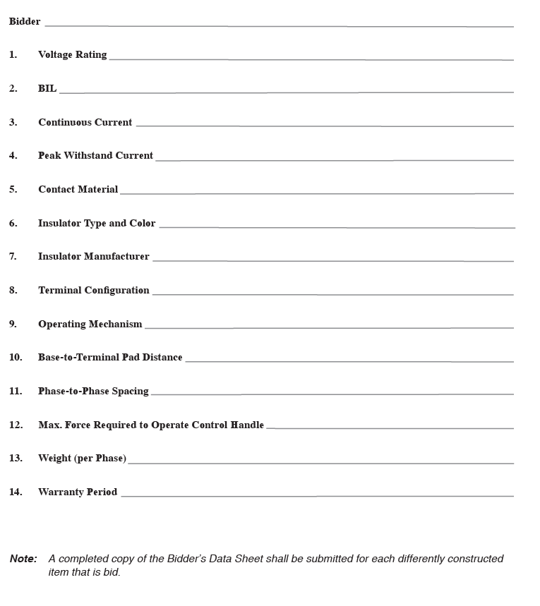
11. Bidders' Data
Bidders shall provide the following data:
11.1 Descriptive literature giving dimensions, construction details, weight and general information on the proposed switches.
11.2 A list of at least three users of the proposed switches, including names and telephone numbers of contacts.
11.3 All information called for on the Bidder’s Data Sheet and its exhibits or attachments.
12. Evaluation of Bids
The following factors will be considered in the evaluation of bids and subsequent bid award:
(1) Base price
(2) Proposed delivery schedule
(3) Conditions of warranty
(4) Test results, if requested
(5) Construction details, such as weight, size, and mounting
(6) Past performance (including, but not limited to, deliveries, engineering assistance and product reliability)
(7) Conformity to Specification
(8) Completeness and quality of responses to the attached Bidder’s Data Sheet
13. Warranty
The Vendor shall warrant all components of each switch supplied against defects in material and workmanship for at least 5 years from the date of shipment.
14. General Bidding Conditions
The attached General Bidding Conditions are made a part of this Specification.