1000782.1 3Ø Station-Type Step-Voltage Regulator 2100-2800 kVA (OA-FA) at 13.2kV
Click here for a PDF of this Material Standard
Revision 2
Jan 9, 2012
1. Scope
This specification covers the requirements for furnishing and delivering a three-phase 60-Hz, mineral-oil-immersed, outdoor, station-type step-voltage regulator rated 2100/2800 kVA (OA/FA) at a nominal voltage of 13.2kV.
2. Material ID Numbers
This Material Standard applies to District Material ID Number 1000782.
3. Reference Standards
The regulator supplied under this Material Standard shall conform to the characteristics, definitions, terminology and requirements of the latest editions, amendments and supplements of:
ANSI/IEEE Standard C57.12.90IEEE Standard Test Code for Liquid-Immersed Distribution, Power, and Regulating Transformers and IEEE Guide for Short-Circuit-Testing of Distribution and Power Transformers
ANSI/IEEE Standard C57.15 IEEE Standard Requirements, Terminology, and Test Code for Step-Voltage and Induction-Voltage Regulators
ANSI/IEEE Standard C57.114 IEEE Seismic Guide for Power Transformers and Reactors
4. Electrical Ratings
4.1 Rated Voltage 13.2kV on grounded or ungrounded system
4.2 BIL Rating 110 kV
4.3 Phase Angle Displacement 0°
4.4 The regulator shall be full capacity with a minimum continuous rating of 2800 kVA (FA) at any output voltage between 12.47kV and 13.2kV without exceeding 65° C temperature rise.
4.5 The range of regulation shall be +10 percent (raise) and -10 percent (lower) with sixteen steps above and below rated voltage. Each step shall cause the output voltage to change by 5/8 percent of the applied input voltage.
4.6 The potential transformer ratio shall be 60:1.
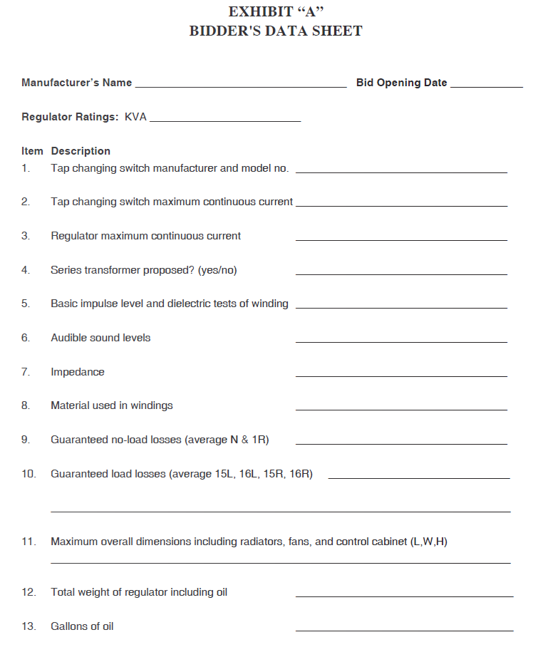
5. Losses
No-load and load losses shall be measured as stated in ANSI/IEEE C57.15. Excitation (no-load) losses and load losses will be evaluated based on the dollar per kilowatt values stated on the Special Provision Sheet. The purchase price will be reduced by an amount equal to the sum of the values of the no-load and load losses that exceed the guaranteed values.
6. Construction
6.1 The regulator shall be painted ANSI 70 gray. The bushings shall be gray porcelain, 15kV class with threaded studs. The District will provide terminals. The bushing arrangement shall be as shown in Figure 4(a) in ANSI/IEEE C57.15.
6.2 Copper windings shall be used.
6.3 A sealed-tank design shall be used. The vacuum tap selector switch may be located in the same tank as the windings.
6.4 The height between the base and the bottom of the bushing porcelain shall not be less than 102 inches.
6.5 All oil-filled compartments shall be designed for full vacuum.
6.6 A 2-inch lower filter-press and oil drain globe-type valve shall be provided, with the oil sampling device located on the discharge side of the valve. A 2-inch nipple and pressure test plug suitable for vacuum filling at the top of the tank shall be provided.
6.7 A hinged access door shall be provided to allow inspection and maintenance of the tap changing mechanism.
6.8 Two copper-faced stainless steel NEMA 2-hole grounding pads shall be located on opposite sides of the tank.
6.9 The regulator shall comply with the seismic requirements of ANSI/IEEE C57.114 for Zone No. 3.
7. Tap Changer and Controls
7.1 Power for the tap changer motor, controls, and fans shall be supplied by internal auxiliary transformers.
7.2 The line drop compensation current transformer shall be installed on bushing L1.
7.3 The tap changing switch shall be vacuum.
7.4 The manual hand crank shall have an interlock which prevents motor operation while the hand crank is engaged.
7.5 The automatic control unit shall be Beckwith Type M-2001B with M-0329B Backup Control Relay.
7.6 The tap changer position indicator shall contain minimum and maximum indicating hands with provisions for resetting.
8. Accessories
8.1 One pressure relief device with an operation indicator visible from the ground shall be mounted on the cover of each oil-filled compartment. It shall contain non-grounded alarm contacts, suitable for operation at 48 or 125 volts DC, wire to terminal blocks in the control cabinet.
8.2 One magnetic-type liquid level indicator with non-grounded alarm contacts suitable for operation at 48 or 125 volts DC shall be installed on each oil-filled compartment and wired to terminal blocks in the control cabinet.
8.3 One oil temperature gauge shall be installed on the main tank. It shall contain non-grounded alarm contacts suitable for operation at 48 or 125 volts DC wired to terminal blocks in the control cabinet.
9. Testing
9.1 Routine and dielectric tests described in ANSI/IEEE C57.15 shall be performed. Three copies of the certified test report shall be provided to the District.
9.2 Quality control impulse tests shall include, as a minimum, one reduced wave and one full wave on the line and neutral terminals of the regulator. Oscillograms are not required with the test report.
9.3 Audible sound tests shall be performed in accordance with ANSI/IEEE C57.12.90. Sound levels with all cooling equipment in operation and the regulator in the tap position with the highest sound level shall not exceed 66dBA.
9.4 Insulation resistance tests shall be made using the Doble method at both 2.5kV and 10kV, with the results at both levels stated on the test report. Results shall be temperature corrected and shall not exceed 0.5 percent when measured at 10kV.
10. Drawings and Instruction Manuals
10.1 Approval drawings shall be submitted to the District within five weeks of the bid award.
10.2 Drawings shall include as a minimum, outline with legend, nameplate, schematics, and wiring. Drawings shall also be provided on Microstation DGN or AutoCAD DWG format.
10.3 Four copies of the instruction manual shall be submitted to the District in addition to one copy shipped with the regulator. In addition to the regulator operating and maintenance instructions each manual shall also contain one set of drawings and catalog information for all accessories including, but not limited to, LTC controls, bushings, gauges, pressure relief device, fans, potential transformer, and control switches.
11. Shipment and Unloading
The regulator shall be shipped, oil-filled, by the date shown on the Special Provision sheet. The Vendor shall be responsible for off-loading the regulator at its destination.