1000554.1 Three-Phase Pad-Mounted Capacitor Bank
Click here for a PDF of this Material Standard
Revision 3
Mar 30, 2018
1. Scope
1.1 This specification covers the requirements for furnishing and delivering a freestanding, self-contained, cabinet enclosed 3-phase air-insulated 15kV load-break elbow cable termination type pad-mounted capacitor bank containing 200 amp interrupter switches, fuses and fixed shunt capacitors.
1.2 This equipment shall be designed for use in 60 hertz, three-phase, 12470 volt grounded-WYE underground distribution systems.
1.3 This equipment shall be designed for outdoor installation and operation. It shall be designed for mounting on a concrete pad.
2. Material ID Numbers
This Specification applies to District Material ID numbers for three-phase pad-mounted capacitor banks:
| MID | Description |
|---|---|
| 1000554 | 300 kVAR (1-100 kVAR capacitor per phase) |
| 1000555 | 450 kVAR (1-150 kVAR capacitor per phase) |
| 1000556 | 600 kVAR (1-200 kVAR capacitor per phase) |
| 1001671 | 900 kVAR (2-150 kVAR or 1-300 kVAR capacitors per phase) |
| 1001694 | 1200 kVAR (2-200 kVAR capacitors per phase) |
| 1001695 | 1350 kVAR (1-150 kVAR and 1-300 kVAR capacitor per phase) |
| 1001696 | 1500 kVAR (1-200 kVAR and 1-300 kVAR capacitor per phase) |
3. General
3.1 The Supplier shall be responsible for ensuring compatibility among all components of the pad-mounted capacitor bank.
3.2 The Supplier shall be solely responsible for the performance of the basic switch and capacitor components as well as the complete integrated assembly as rated.
3.3 Upon the District's request, the Supplier shall provide sufficient notice to allow the District or its representatives to inspect the unit during its manufacture and to witness any or all tests performed on it.
3.4 Bidders shall furnish certified tests establishing the electrical ratings of the pad-mounted capacitor bank, including ratings of the basic switches, fuse components and capacitors that are being bid.
3.5 Bidders shall provide product information for the pad-mounted capacitor bank with the initial bid, including, but not limited to, the items listed in section 22. of this specification.
4. Reference Standards
Except as modified by this specification, the pad-mounted capacitor bank furnished shall comply with the requirements of the latest revisions of all applicable ANSI, IEEE and NEMA standards in addition to the standards listed below:
| ANSI/IEEE 18 | IEEE Standard for Shunt Power Capacitors |
| ANSI/IEEE 1036 | IEEE Guide for Application of Shunt Power Capacitors |
| ANSI/IEEE C37.73 | IEEE Standard Requirements for Pad-Mounted Fused Switchgear |
| ANSI C57.12.28 | ANSI Standard for Switchgear and Transformers Pad-Mounted Equipment Enclosure Integrity |
| ANSI C2 | National Electrical Safety Code |
5. Electrical Ratings
5.1 Pad-Mounted Gear
| Power Frequency | 60Hz |
| Nominal Voltage | 12.47kV |
| Maximum Voltage | 13.7kV |
| BIL | 95kV |
| Main Bus, Continuous Current | 200A |
5.2 Interrupter Switches
| Power Frequency | 60 Hz |
| Continuous Current | 200A |
| Capacitive Current Interrupting | 200A for 200 operations |
| Operating Voltage | 120 VAC |
| Voltage Rating, Maximum | 15kV |
| Fault Duty | 9000A momentary |
| BIL | 95kV |
5.3 Capacitors
| Power Frequency | 60Hz |
| Rated Voltage | 7.2kV, RMS |
| BIL | 95kV |
6. Capacitor Tanks and Construction
6.1 Tanks shall be of welded steel construction free from leaks and seepage.
6.2 Tanks shall be properly cleaned and painted for protection against severe atmospheric conditions, oxygen, acid, salts and alkalis.
6.3 All external fittings, cover bolts, washers and nuts shall be stainless steel.
6.4 Clamping devices shall be of corrosion resistant material.
6.5 Tank finish shall be ANSI #70 light gray, Munsell 5BG7.0/0.4.
6.6 Capacitors shall be of the all-film dielectric type.
6.7 Capacitor fluid shall be either Dielektrol II, Selectrol II or District approved equivalent.
7. Capacitor Bushings
7.1 Each capacitor shall have two bushings.
7.2 The creepage distance of each bushing shall be a minimum of 11 inches.
7.3 Each bushing shall be rated at a minimum of 95kV BIL.
7.4 Each bushing shall be made of glazed, wet-processed porcelain, or District approved equal. The District will be the sole judge of whether non-porcelain bushings are acceptable.
7.5 Each bushing terminal shall be of the clamp connector type and shall accommodate copper conductors in AWG sizes #8 solid - #2 stranded.
7.6 Each bushing shall be fitted with covers to prevent incidental contact from wildlife.
8. Interrupter Switches
8.1 Interrupter switches shall have ratings as specified in section 5.2 of this specification.
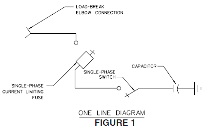
8.2 Interrupter switches shall be in series with fuses, see one-line diagram, Figure 1.
8.3 Interrupter switches shall have a manual trip lever, which is easily accessible for manual operation by hot stick.
8.4 Interrupter switches shall not use oil or SF6 insulation.
8.5 Interrupter switches shall use vacuum for the interrupting medium.
8.6 The interrupter switch shall be maintenance-free.
8.7 The current required for opening or closing the interrupter switch shall not exceed 4 amps.
9. Fuse Mountings
9.1 The fuse compartment shall be equipped with mountings to accommodate three S&C SML-20 power fuseholders designed for S&C SMU-20 power fuses. The fuse mounts shall utilize S&C live parts unless otherwise approved by the District.
9.2 FUSEHOLDERS AND FUSES SHALL NOT BE PROVIDED UNDER THIS SPECIFICATION.
9.3 Power fuse mountings may have a built-in load-break device in the contact assembly, but are not to be used to break capacitive load.
9.4 Live-switching shall be accomplished by the interrupter switches.
9.5 A storage rack shall be provided in each fuse compartment to accommodate up to three S&C SMU-20 fuse refill units.
10. Fuses and Fuse Holders
10.1 S&C SML-20 fuseholders and SMU-20 fuses (200A maximum) shall be supplied by the District.
10.2 Fuses will be in series with the switches (see one-line diagram, Figure 1).
10.3 NEMA grade GPO-3 red fiberglass reinforced polyester barriers will be used between fuse positions.
10.4 Hot stick removable NEMA grade GPO-3 red fiberglass reinforced polyester access barriers will be used.
11. Fuse Handling Tool
One S&C GrapplerTM fitting, or District approved equivalent, for attachment to a hot stick for handling S&C SML-20 fuse holders, shall be furnished attached to a storage rack inside the fuse side of each pad-mounted capacitor bank.
12. Controls and Control Cables
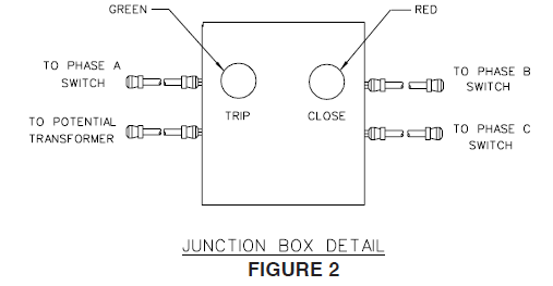
12.1 A push button station shall be installed with a red button for closing and a green button for opening (see junction box detail, Figure 2).
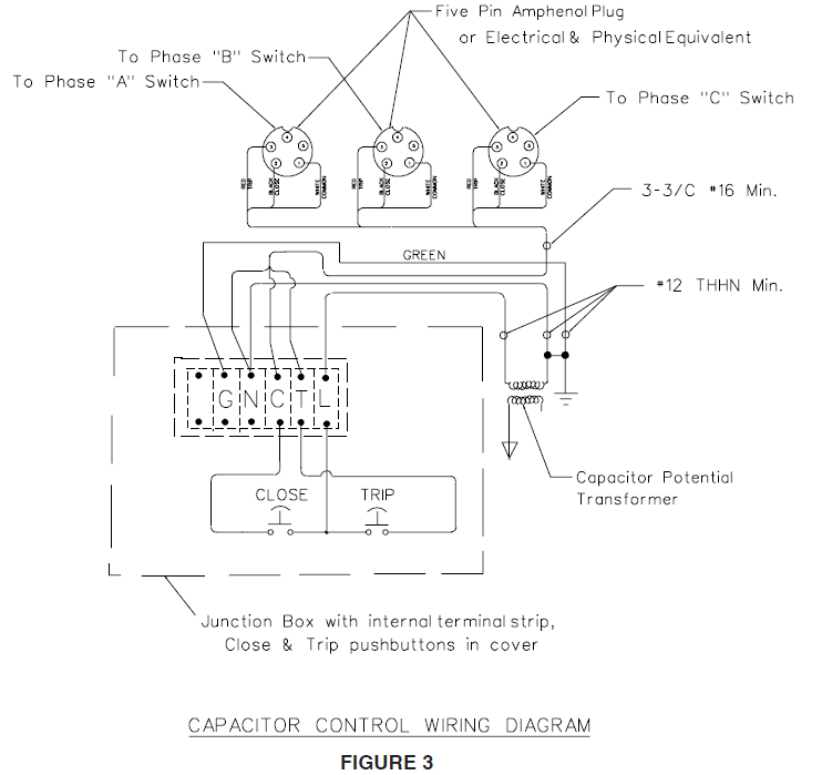
12.2 The control cables shall contain multicolored, current carrying conductors (black, white, and red or the equivalent approved by the District), and green non-current carrying safety grounds.
12.3 The black and white conductors shall be used to open and close the switches.
12.4 Manufacturer's variances may be allowed once drawings showing the variances are submitted to the System Protection and Control group for review, and are approved.
13. Potential Transformer
13.1 The potential transformer shown on the control wiring diagram (Figure 3) shall be sized to adequately provide for opening, closing and control power/voltage.
13.2 The potential transformer shall contain no insulating oil.
13.3 The potential transformer shall be an ABB VIZ-11, line-to-ground unit with one fuse, rated 60 Hz, 110kV BIL, primary voltage 7200/12470GY, secondary voltage 120, winding ratio 60:1.
13.4 The fuse for the potential transformer shall be provided.
13.5 The potential transformer shall be mounted in such a manner that it is easily accessible by field personnel.
13.6 All exposed bus work and energized contacts shall be insulated to avoid incidental contact.
14. Enclosure
14.1 General
14.1.1 The pad-mounted capacitor bank cabinet shall be of unitized construction (not structural frame and bolted sheet).
14.1.2 The cabinet, including the doors, shall be of 12 gauge steel sheet.
14.1.3 All structural joints and butt joints shall be welded, all welding shall be MIG, and the external seams shall be ground flush and smooth.
14.1.4 The base shall be square and smooth to enable it to rest solidly on a smooth concrete surface. The base shall consist of continuous 90° flanges, 1 inch minimum width, turned inward and welded at the corners for bolting to a concrete pad.
14.1.5 The cabinet shall have adequate size and strength for fuse handling, fuse exhaust and venting, and shall withstand all pressure buildup during interruption without permanent distortion or damage to any portion of the structure.
14.1.6 The cabinet shall be so designed to permit free flow ventilation from bottom to top to minimize condensation without sacrificing security.
14.1.7 The cabinet shall meet or exceed ANSI C57.12.28 tamper resistance requirements.
14.2 Roof
14.2.1 The cabinet roof shall be constructed so as to shed water. If two roofs are used, water shall not collect at their intersection.
14.2.2 The roof shall be undercoated with a heavy coat of an insulating "no-drip" compound to prevent condensation of moisture on its inside surface.
14.3 Access
14.3.1 Access into the cabinet, after installation, shall be through the doors to the front and rear compartments only.
14.3.2 The design of the cabinet interior shall be such that all components are visible without disassembly in order to facilitate inspection and cleaning.
14.4 Doors
14.4.1 All exterior doors shall include a three-point latching system that requires doors to be latched before the padlock shackle can be inserted. The door handles shall be padlockable with a padlock having a 3/8" diameter shackle and shall use a hood to protect the padlock from tampering. The door latching system shall require only a single padlock per door or per set of double doors. Each door handle shall be provided with a recessed penta head bolt as part of its security system. The penta head bolt shall be of a size compatible with District penta head bolt socket wrenches, i.e., 0.840 inches flat-to-opposite peak.
14.4.2 Doors shall be bulkhead type, side-hinged to swing open horizontally. Top-hinged, clam shell type doors are unacceptable.
14.4.3 Doors shall be equipped with stainless steel hinge assemblies and hinge pins.
14.4.4 Each door shall be equipped with a zinc-nickel plated steel or hot-dip galvanized steel door-holder located above the door opening. These holders shall be hidden from view when the door is closed. It shall not be possible for the door-holders to swing inside the enclosure. The door-holders shall hold the doors open at an angle of at least 103° and at most 120°.
14.4.5 All locking mechanisms shall use captive hardware to avoid misplacement.
14.5 Finish
14.5.1 The finish of the switchgear cabinet shall meet or exceed the requirements of ANSI C57.12.28, latest revision. Combined primer and topcoat thickness shall be no less than 3.0 mils. Paint and primer shall be lead free. A certified test abstract to indicate compliance with these requirements shall be furnished upon request.
14.5.2 The topcoat of the finish shall be dark green Munsell No. 7GY 3.29/1.5.
14.5.3 A resilient closed-cell material, such as PVC gasket, shall be applied to the entire underside of the enclosure bottom flange to protect the finish on this surface from scratching during handling and installation. This material shall isolate the bottom flange from the alkalinity of a concrete foundation to help protect against corrosive attack.
14.6 Lifting Provisions
14.6.1 The enclosure shall be equipped for lifting from above.
14.6.2 If the enclosure is equipped with lifting tabs then the lifting tabs shall be removable.
14.6.3 If lifting tabs are used, a resilient material shall be placed between the lifting tabs and the enclosure to prevent the tabs from scratching the enclosure finish. To help retard corrosion, the resilient material shall be closed-cell to prevent moisture from being absorbed and held between the tabs and the enclosure in the event that the lifting tabs are not removed.
14.7 Dimensions
14.7.1 The maximum external dimensions of the pad-mounted capacitor bank enclosure's footprint shall not exceed 6'-0" wide x 6'-0" deep. The enclosure's height shall not exceed 6'-0" high (not including lifting tabs).
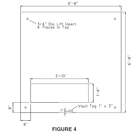
14.7.2 The enclosure shall be dimensioned such that it will fit over the 46 inch wide x 18 inch deep cable opening in the District's standard 6'-8" x 6'-8" vault cover, illustrated in Figure 4.
15. Buses
15.1 All buses shall be of copper or aluminum.
15.2 All joints shall have suitable hardware and treatment to prevent harmful oxidation and loss of optimum contact pressure.
15.3 Bus and interconnections shall withstand the stresses associated with short circuits up through the maximum rating of the pad-mounted capacitor bank.
15.4 Bus work shall be protected from incident contact and wildlife animals.
16. Universal Bushing Wells and Parking Stands
16.1 One each universal load-break bushing well with dust cap shall be provided and factory-installed for each cable termination phase position. The District will provide and install the necessary load-break bushing inserts.
16.2 Bushing wells shall be rated 8.3/14.4kV 200A continuous and shall conform to ANSI/IEEE 386, latest revision.
16.3 Each cable termination phase position shall be provided with a load-break elbow parking stand.
17. Barriers
17.1 All enclosures shall include compartmentalization between the switch, fuse, 15kV cable termination, and capacitor areas.
17.2 Insulating interphase and end barriers of NEMA grade GPO3 red fiberglass-reinforced polyester shall be provided for each fuse position.
17.3 Each fuse position shall be provided with dual purpose front barriers of NEMA grade GPO3 red fiberglass reinforced polyester to meet NESC Rule 381G of ANSI C2.
17.3.1 These barriers, in their normal vertical hanging positions, shall guard against inadvertent contact with live parts. An upper window panel shall be provided to allow viewing of the fuse position without removing the barriers.
17.3.2 It shall be possible to easily lift out the dual purpose front barriers in the fuse compartments and then insert them in the open gap when the fuses are in the disconnect position.
17.3.3 The dual purpose front barriers shall be designed such that the enclosure doors can be closed and locked with the fuses open and the barriers in the slide-in position.
17.3.4 The dual purpose front barriers shall prevent inadvertent contact with energized parts at the top of the fuse positions when barriers are in the slide-in position.
17.4 An insulating NEMA grade GPO3 red fiberglass-reinforced polyester hanging barrier shall be provided in front of the capacitor bank compartment of the enclosure. This barrier shall be equipped for easy removal and installation.
18. Grounding Pads
18.1 A ground connection pad shall be provided in each compartment of the pad-mounted gear. The pads shall be welded to the interior of the enclosure near the cable entrances.
18.2 The pads shall be of unpainted copper-faced steel, unpainted stainless steel or unpainted galvanized steel. The pads shall be a minimum of 2 inches x 3-1/2 inches with two 1/2-13 UNC tapped holes, a minimum 7/16 inch deep, spaced 1-3/4 inches center-to-center.
18.3 The grounding pads shall be capable of carrying the fault duty of the pad-mounted capacitor bank.
19. Labeling
19.1 Nameplate
The outside of each door, or set of double doors, of the pad-mounted capacitor bank enclosure shall be provided with a durable corrosion-resistant nameplate indicating:
- Name of manufacturer
- Date of manufacture
- Model no.
- Catalog no.
- Serial no.
19.2 Ratings Label
The inside of each door, or set of double doors, shall be provided with a ratings label. This label shall include the ratings required in section 5. of this specification.
19.3 Connection Diagram
The inside of each door, or set of double doors shall be provided with a three-line connection diagram of the padmounted capacitor bank. The diagram shall show the interrupter switches, fuses with integral load interrupters and bus.
19.4 Phase Identification
The bushings shall be labeled "A", "B", "C" left to right when facing the front of the enclosure. These labels shall be located on the interior of the enclosure.
19.5 Warning Labels
The manufacturer shall not install exterior or interior warning labels but shall leave space for the District's labels as indicated herein.
19.5.1 The District will provide and install a warning label conforming to the requirements of the latest revision of District Material Standard 890534.1 on the outside of each door of the enclosure.
19.5.2 The District-installed warning labels will be conspicuously located on the upper half of the doors. The top edge of the warning labels will be in alignment with the top edge of the doors.
19.6 Danger Labels
The manufacturer shall not install exterior or interior danger labels but shall leave space for the District's labels as indicated herein.
19.6.1 The District will provide and install a danger label conforming to the requirements of the latest revision of District Material Standard 890526.1 on the inside of each door of each compartment and on the front and back of each front hanging insulating barrier in each compartment.
19.6.2 The District-installed danger labels will be conspicuously located on the upper half of the doors and barriers.
19.7 Do Not Use Elbows to Switch Label
The manufacturer shall install, above the bushings, a label that states "DO NOT USE ELBOWS TO SWITCH ENERGIZED CAPACITORS".
19.8 Non-PCB Labels
19.8.1 A NON-PCB label shall be affixed to one end of the lower half of each capacitor tank. The label shall indicate that the capacitor dielectric fluid contained less than 1 PPM PCB at the time of manufacture.
19.8.2 The label shall have a UV-resistant blue opaque background, Pantone Color 293 C, with white reflective reversed out copy. The label shall conform to the latest revision of District Material Standard No. 1000212.1 or shall be a District-approved equal label.
20. Instruction Manual
One instruction manual covering installation, operation and maintenance of the equipment shall be provided with each cabinet. This manual shall be packaged in a weatherproof bag or envelope and secured on the inside of the door of the far right-hand compartment on the cable termination side of the cabinet.
21. Certified Test Reports
21.1 All Bidders shall provide certified test reports verifying that the equipment meets or exceeds the electrical ratings, tamper resistance and finish required by this specification.
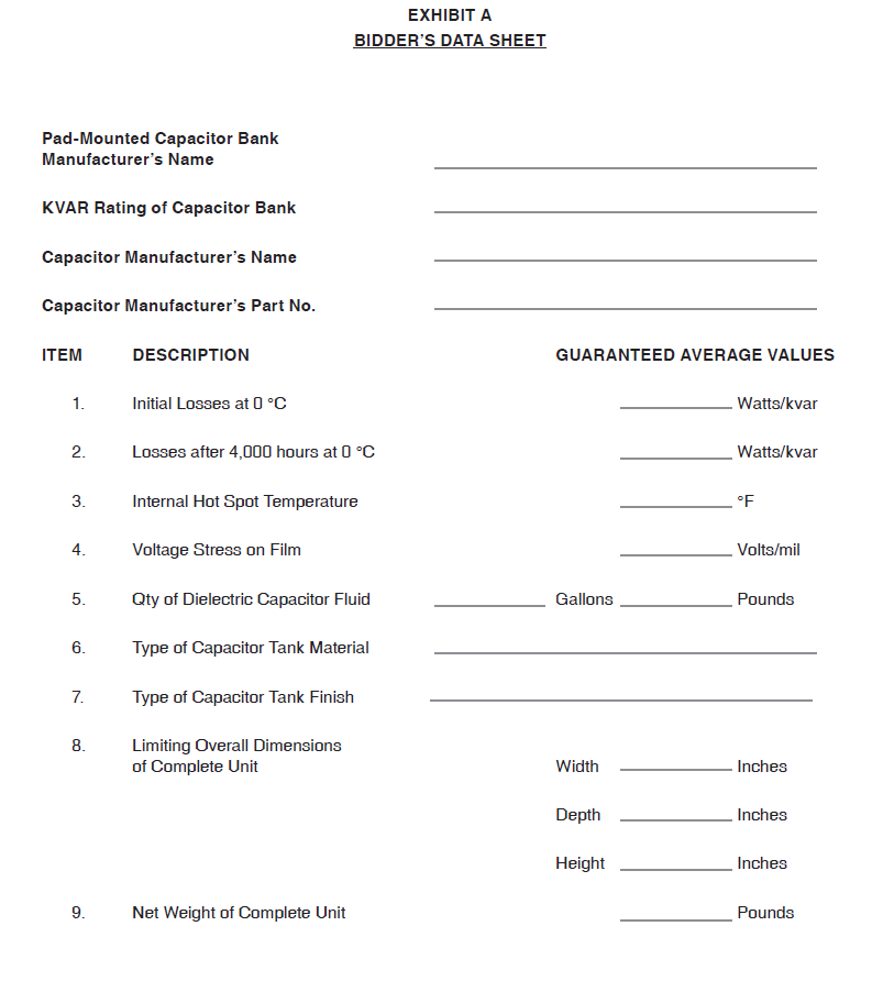
21.2 All Bidders shall furnish one certified copy of the test report for Capacitor Unit Power Loss (initial and after 4,000 hours of operation) and Voltage Stress (volts per mil) at rated voltage on film portions of the dielectric.
21.3 The Supplier shall furnish one certified copy of the test reports for each bank. These tests, as a minimum, shall include the routine tests described in ANSI/IEEE 18, latest revision.
21.4 The above reports shall be mailed to:
PUD No. 1 of Snohomish County
Attention: System Planning & Protection O1
PO Box 1107
Everett, WA 98206-1107
22. Bidders' Data
In addition to the information required on the attached Exhibit A, Bidder's Data Sheet, each Bidder shall submit the following with their proposal for each model of pad-mounted capacitor bank:
22.1 A list of all proposed changes, additions or exceptions to this specification along with adequate explanations for each departure from the specification
22.2 Electrical specifications including a statement of all electrical tests given and whether these tests apply to all units or only to sample units
22.3 The names of the manufacturers and the electrical specifications for all key components used in the assembly of this equipment, including but not limited to, fuse mounts, switches, capacitors and potential transformer
22.4 Proof that the manufacturer of the pad-mounted capacitor bank is currently OEM-certified by the manufacturers of the key components
22.5 Outline drawings with internal, external and overall dimensions
22.6 Information concerning construction details
22.7 Method of latching and stops on doors
22.8 Type of material and method of attachment of all labels
22.9 One instruction manual covering installation, operation and maintenance of the equipment
22.10 Completed Material Safety Data Sheet for manufacturer's capacitor fluid
22.11 Completed Material Safety Data Sheet for each distinct formulation of insulating oil used in potential transformers supplied as part of the pad-mounted capacitor bank assembly
23. Warranty
23.1 The Supplier shall guarantee all parts of the pad-mounted capacitor bank against defects in material and workmanship for a minimum of 12-months from the date of energization or 18-months from the shipping date, whichever comes first.
23.2 Upon written notice from the District, the Supplier shall immediately repair or replace, at his own expense, all or any part of the pad-mounted capacitor bank that may prove to be defective during the period of this guarantee, whether installed initially or installed as repair or replacement under this guarantee.
23.3 The Supplier further guarantees that the warranty for repaired or replaced material shall be of an equal duration as the original warranty period and shall start upon acceptance of such repaired or replaced material.
24. Shipment
24.1 Shipment shall be:
FOB PUD No. 1 of Snohomish County
Operations Center Receiving
1802 75th Street SW
Everett, WA 98203-6264
24.2 Equipment damaged in shipment will be refused on delivery and it will be the Supplier’s responsibility to arrange the prompt repair or replacement to the standards of new equipment. The Supplier will not be relieved of the responsibility of delivering undamaged equipment, even if the damage is internal, or otherwise goes undetected and the nature of the damage remains unknown until the equipment is energized and tested.
24.3 Each pad-mounted capacitor bank shall be completely assembled and packaged in accordance with good commercial practice to ensure safe delivery without damage to the finish or any other part of the unit.
24.4 Provisions shall be made to protect pad-mounted capacitor banks shipped on flatbed trucks from contamination of the cabinet exterior and interior from rocks, dirt, insects and other foreign materials encountered in shipment.
24.5 Each pad-mounted capacitor bank shall be shipped on a nonreturnable wood pallet designed for handling with a forklift. Pallets shall have a minimum of 3-1/2 inches of vertical clearance for the forks. Pallets shall be of adequate strength to withstand normal shipping and handling of the cabinet.
24.6 Pad-mounted capacitor banks shall be shipped so that they may be removed from the truck or trailer by forklift.
24.7 No material or other equipment shall be stacked or carried on top of the cabinet.
25. Evaluation of Bids
The following factors will be considered in the analysis and evaluation of bids and subsequent bid award:
25.1 Price
25.2 Past performance of Bidder and product
25.3 Construction and Operation details
25.4 Adherence to specifications
25.5 Manufacturing ability
25.6 Delivery schedule
26. Inspection
After delivery, inspection shall be in accordance with Section 2 of the District’s Purchase Order Terms and Conditions, latest revision. If returning rejected equipment to the supplier, the shipping costs will be at the supplier’s expense.
27. Correction of Deficiencies and Nonconformities
Any opportunity for the Supplier to correct deficiencies and nonconformities will be at the sole discretion of the District and at the sole expense of the Supplier. If the District elects to allow corrections, mutual arrangements shall be made for their completion. Any subsequent testing required due to deficiencies and nonconformities will be at the Supplier's expense. All shipping costs associated with correction of deficiencies and nonconformities will be at the Supplier's expense.
28. General Bidding Conditions
The attached General Bidding Conditions are made a part of this specification.