832114.1 15kV TRXLP Insulated, Unjacketed Concentric Neutral Underground Power Cable
Click here for a PDF of this Material Standard
Revision 11
Sept 19, 2011M
1. Scope
1.1 Description
This specification covers the technical requirements for 15kV rated unjacketed concentric neutral underground distribution power cable. The cable shall consist of one tree-retardant cross-linked polyethylene insulated central conductor with a helically applied copper concentric neutral conductor over the insulation shield.
1.2 Material ID Numbers
This specification applies to the following District Material ID Numbers:
832114 2 AWG aluminum 7 strand 15kV cable
832148 1/0 AWG aluminum 19 strand 15kV cable
832156 350 kcmil aluminum 37 strand 15kV cable
1.3 Applications
The cable shall be suitable for use in one, two and three-phase residential and commercial applications on the District’s 60 hertz 12470 Grd Y/7200 volt primary underground distribution systems.
1.4 Service Environment & Operating Requirements
1.4.1 The cable shall be suitable for aerial, direct burial, and conduit installations in wet and dry locations with maximum normal conductor operating temperatures to 90°C in accordance with ANSI/ICEA S-94-649-2013. The cable shall be suitable for a minimum installation temperature of -10°C.
1.4.2 The cable shall be designed and constructed such that it will operate satisfactorily at emergency overload conductor operating temperatures to 130°C and short circuit conductor operating temperatures to 250°C as defined by ANSI/ICEA S-94-649-2013.
1.5 Plant Inspections
1.5.1 Observation of the cable manufacturing, including inspection and testing, by the District’s representative, shall be at the option of the District. When requested by the District, the Manufacturer shall notify the District’s purchasing department of production and test schedules at least two weeks prior to the start of cable production. Travel shall be at the District’s expense.
1.5.2 The District’s representative shall have right of access to the manufacturing plant. The purpose of such access is to perform a plant audit that shall include but not be limited to verification that the Manufacturer’s process controls are documented, effective, and in use during cable production, and for plant inspection for cleanliness and quality control.
1.6 Language
All information communicated to the District shall be in the English language and shall be in customary English units, e.g., feet, inches, pounds. Metric units and/or other languages are not acceptable.
2. Reference Standards
Reference is made in this specification to the following standards, the latest editions, amendments, and supplements of which shall apply, unless otherwise stated in this specification or in associated purchasing documents:
AEIC CS8-13 Specification for Extruded Dielectric Shielded Power Cables Rated 5 Through 46kV
ASTM Standards As referenced
ANSI/ICEA S-94-649-2013 Standard for Concentric Neutral Cables Rated 5,000 - 46,000 Volts
ICEA T-31-610 Guide for Conducting a Sealed Water Penetration Resistance Test for Sealed Conductor
ISO-9002 Quality Systems - Model for Quality Assurance in Production, Installation and Servicing
NEMA WC 26-2008 Binational Wire and Cable Packaging Standard
3. Definition of Terms
The following definitions pertain to this specification:
AEIC:Association of Edison Illuminating Companies
ANSI: American National Standards Institute
ASQC:American Society for Quality Control
ASTM:American Society for Testing and Materials
CTR: Manufacturer’s Certified Test Report
CV: Continuous vulcanization
EC: Extra-Clean
ICEA: Insulated Cable Engineers Association
ISO: International Organization for Standardization
Mil(s):One thousandth of an inch
Triple-Tandem Extrusion: A process in which the conductor shield is applied in one extrusion head and then the insulation and insulation shield are applied in a second extrusion head a short distance away
True-Triple Extrusion:A process in which the conductor shield, insulation and insulation shield are applied in one extrusion head
4. Manufacturing Method
4.1 Insulation Material Handling
All processing and handling from pellet production through the CV process shall be in accordance with EC grade requirements. A pellet inspection system is an acceptable method to remove foreign matter from the pellet feedstock, if used, 100-percent inspection is required.
4.2 Extrusion
4.2.1 The conductor shield, insulation, and insulation shield shall be applied in a triple extrusion process. A true-triple extrusion process is preferred. A triple-tandem extrusion process may be acceptable.
4.2.2 All changes or alterations to the critical process parameters of the extrusion line shall be logged in the production log.
4.3 Curing
The curing system during extrusion shall be a nitrogen or inert gas system.
4.4 Cooling
A moisture-free cooling process is preferred and may be given an evaluation advantage.
5. Construction
The cable furnished under this material standard shall consistently comply with all of the applicable test requirements specified in Section 8. of this material standard.
5.1 Central Conductor
The central conductor shall be uncoated aluminum 1350, in accordance with ASTM B230, stranded as specified in Section 5.1.1 of this specification. Aluminum rod from which the conductor is drawn shall be free of defects and corrosion, cleaned of oil and contaminants, and purged of cleaning solvents prior to the drawing process.
The use of lubricant during the drawing process is acceptable. The conductor surface shall be smooth.
5.1.1 Stranded Conductor
Stranded aluminum conductor shall be either hard-drawn (1350-H19) or 3/4 hard-drawn (1350-H16 or 1350-H26), Class B concentric lay, compressed 3-percent, in accordance with ASTM B230, B231 and B609. The number of strands per conductor shall be as shown in Figure 1 of this specification. Compact stranded conductor is not acceptable; bids offered for this type of cable will be considered nonresponsive.
5.2 Conductor Shield
5.2.1 The central conductor shield shall be extruded directly over the conductor and shall be supersmooth, extra-clean, black, thermosetting, semiconducting cross-linked polyethylene: Union Carbide HFDA-0800, HFDA-0802, Nova-Borealis LE0504, General Cable Corporation XFB 550A or District approved equal.
5.2.2 The conductor shield shall meet the applicable requirements of ANSI/ICEA S-94-649-2013, Part 3, and AEIC CS8-13, Section 3.0, with the exception that a semiconducting tape between the conductor and the extruded conductor shield material is unacceptable.
5.3 Insulation
5.3.1 The insulation shall be extruded directly over the conductor shield layer and shall be extra-clean, tree-retardant cross-linked polyethylene (TRXLPE): Union Carbide HFDB-4202 Natural EC, AT Plastics PowerGuardTM 320TR, Nova-Borealis Super TRTM LE4212 or District approved equal.
5.3.2 The insulation shall meet the applicable requirements of ANSI/ICEA S-94-649-2013, Part 4, and AEIC CS8-13, Section 4.0.
5.3.3 The nominal thickness of the insulation shall be 175 mils as specified for the 100-percent insulation level for 15kV cable in sizes 2 AWG - 1000 kcmil in ANSI/ICEA S-94-649-2013, Table 8-1. The tolerance limits for the over-insulation cable diameter shall be as specified in ANSI/ICEA S-94-649-2013, Appendix C.
5.4 Insulation Shield
5.4.1 The insulation shield shall be extruded directly over the insulation and shall be clean, lump-free, black, semiconducting cross-linked polyethylene: Union Carbide HFDC-0692, HFDC-0693C, General Cable LS 567A, Nova-Borealis LE310MS or District approved equal.
5.4.2 The insulation shield shall meet the applicable requirements of ANSI/ICEA S-94-649-2013, Part 5, and AEIC CS8-13, Section 5.0.
5.4.3 The insulation shield shall be legibly identified as semiconducting by surface printing; indent printing is unacceptable for labeling the insulation shield layer.
5.4.4 The insulation shield shall strip freely and cleanly from the underlying insulation using standard stripping tools. Any conductive material left after stripping shall be easily removable by light rubbing with a cloth impregnated with American Polywater type HP or equivalent cable cleaning solvent. The insulation shield strippability shall meet the applicable requirements of AEIC CS8-13, Section 5.4.
5.5 Concentric Neutral Conductor
5.5.1 A concentric neutral conductor consisting of annealed, uncoated copper wires in accordance with ANSI/ICEA S-94-649-2013, Part 6, and Section 5.5.3 of this specification, shall be applied directly over the semiconducting insulation shield.
5.5.2 The wires of the concentric neutral shall be applied with a left-hand lay not less than six nor more than ten times the diameter of the cable over the concentric neutral wires. There shall be equal spacing between concentric neutral wires.
5.5.3 Cable with a central conductor size of 2 or 1/0 AWG aluminum shall have a full concentric neutral and cable with a central conductor size of 350 kcmil aluminum shall have a one-third concentric neutral as shown in Figure 1.
6. Cable Identification
6.1 The center strand of stranded conductor cable shall be indent printed with the Manufacturer’s name and year of manufacture at regular intervals with no more than 12 inches between repetitions in accordance with ANSI/ICEA S-94-649-2013, Part 8.2.3.
6.2 The outer surface of the insulation shield of each cable shall be durably and legibly marked throughout its length in accordance with ANSI/ICEA S-94-649-2013, Part 8.2.2. Identification marking shall be by surface printing only with white or silver colored ink.
6.3 Sequential footage numbers shall be clearly printed throughout the cable length at 2 foot intervals in accordance with ANSI/ICEA S-94-649-2013, Part 8.2.4. Sequential footage numbers shall not be repeated on any single order. Sequential footage numbers shall be by surface printing only with white or silver colored ink.
7. Quality Assurance
7.1 Quality System
The cable Manufacturer shall have a quality system in place that meets the requirements of ISO-9002, latest edition.
7.2 Plant Certification
To qualify as a Bidder the following information shall be submitted for the specific cable manufacturing plant where the cable will be made: (Note: The District encourages cable Suppliers to submit this information in advance of the bid quote. See Section 8.4.2 for mailing address.)
7.2.1 Plant location
7.2.2 Description of the extrusion equipment used, including positioning of extruders
7.2.3 Description of the “dry” curing process and equipment used
7.2.4 Description of the cooling down process used
7.2.5 Description of the pellet inspection process used
7.2.6 Description of the pellet handling system used from the shipping vehicle to the extruder
7.2.7 Description of the statistical quality control method used
7.2.8 List of previous customers supplied from this plant
8. Testing by the manufacturer
8.1 Qualification Tests
One certified copy of the results of AEIC CS8-00 and ANSI/ICEA S-94-649-2013 qualification tests on the specified cable shall be provided. Cable with a number 1/0 AWG conductor size is the preferred size for the qualification tests.
8.2 Production Sampling Tests
Production sampling tests shall be made in accordance with the applicable parts of AEIC CS8-13 and ANSI/ICEA S-94-649-2013.
8.3 Tests on Completed Cables
Tests on completed cable shall be made in accordance with the applicable parts of ANSI/ICEA S-94-649-2013. Electrical tests shall be performed on each shipping reel.
8.4 Test Reports
8.4.1 The cable Manufacturer shall furnish the District with one certified copy of all applicable production tests in accordance with ANSI/ICEA S-94-649-2013, AEIC CS8-13 and this specification. Data recorded for Qualification Tests shall also be sent to the District. One certified copy of the dimensional measurements and reports of all test data shall be furnished for each reel of cable to be shipped. All tests must demonstrate compliance of the cable to be shipped with all applicable requirements.
8.4.2 One copy of each certified test report shall be sent to:
Snohomish County Public Utility District No. 1
Attn. Engineering Standards
P.O. Box 1107
Everett, WA 98206-1107
9. Acceptance Tests by the District
9.1 Sampling By the District
The District may take cable samples from each shipping reel of received cable or may request a sample from each reel of cable to be shipped. If cable samples are requested by the District they shall be shipped concurrent with the regular cable shipment. If requested, cable samples shall consist of one 2-foot length of cable taken from the trailing cable end of each shipping reel, appropriately identified with the reel and master reel number of the reel from which they were taken. Samples shall be taken such that a cable shipping length occurs between each sample. One copy of the associated certified test report shall be sent with any cable samples requested. If cable samples are requested, the District will inform the Manufacturer where to ship them at the time of the request.
9.2 Performance Acceptance Tests
Performance acceptance tests may be conducted on samples from each reel of cable. The testing and examinations of cable samples may be performed by the District or its authorized agent. All test procedures, examinations, and their results shall conform to the applicable parts of ANSI/ICEA S-94-649-2013 and AEIC CS8-13 except as specifically noted. Failure of a sample to satisfy the requirements of any section of this specification may be cause for rejection of that shipping reel of cable. The District reserves the right to return, at the Supplier’s expense, any cable not meeting the requirements of this specification.
10. Shipment and Reels
10.1 Packing and Sealing
10.1.1 Cable shall be supplied in one continuous length for each reel. Cable length per reel shall be as specified in Figure 2 of this specification.
10.1.2 Each end of the cable shall be firmly and properly secured to the reel. Care shall be taken to prevent looseness of reeled cable. The cable end attached through the interior of the reel shall be fastened in such a manner that it remains attached as the cable is dispensed from the reel and does not interfere with other reels or waste cable.
10.1.3 There shall be a minimum 2-inch clearance between the outer edge of the reel flange and the surface of the outermost layer of cable.
10.1.4 Watertight seals shall be applied to all cable ends to prevent entry of moisture during transit and outside storage. All reels shall have Level 2 flexible film type protection over the outer layer of cable in accordance with NEMA WC 26-2008, Section 4.1.
10.2 Reels
Unless otherwise specified on the Special Provisions sheet, all reels shall:
10.2.1 Be standard nonreturnable wood reels conforming to NEMA WC 26-2008, unless otherwise stated in this specification or authorized by the District
10.2.2 Be free of damaging protrusions, e.g., nails, staples, etc.
10.2.3 Use steel bushings to line reel arbor holes if the gross weight of the reel exceeds 2,500 pounds
10.2.4 Have minimum drum diameters as specified in NEMA WC 26-2008, Section 3 (14 x cable OD)
10.2.5 Have dimensions and tolerances as specified in Figure 2 of this specification
| Cable Legnth | Reel Dimensions | |||||
|---|---|---|---|---|---|---|
| Conductor Size | Footage Per Reel | Tolerance | Max Flange Dia. | Max. Overall Width | Min. Drum Dia. | Arbor Hole Dia. |
| 2 AWG | 3000' | +10 / -0% | 50" | 38.5" | 12 x Cable OD | 3.06" |
| 1/0 AWG | 2500' | +10 / -0% | 50" | 38.5" | 12 x Cable OD | 3.06" |
| 350 kcmil | 2000' | +10 / -0% | 58" | 40.0" | 12 x Cable OD | 3.06" |
10.3 Marking on Reels
Reel information shall be permanently marked on two tags of durable weather-resistant material. One tag shall be securely affixed to the outside of the cable reel flange and the second tag shall be securely affixed to the inside of the reel flange or to the reel cable covering. Each reel tag shall be marked with the information specified in AEIC CS8-13, Section 12.3.
10.4 Bar Coding
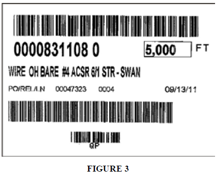
10.4.1 Each reel of cable shall be bar coded. Bar codes shall be formatted similar to Figure 3 of this specification.
The District and the supplier that will be providing the cable shall reach agreement on the details of a bar code label that satisfies the District's needs after the contract is awarded and before the cable is shipped.
10.4.2 Bar codes shall conform to ANSI/AIM BC2-1995 Code 39 bar code standard.
10.4.3 The bar code label shall be a minimum of 4" wide x 3" high. It shall be made of durable, weather resistant, premium polyethylene stock. The reel marking information required in Section 10.3, above, may be included on the bar code label.
10.4.4 Bar code labels shall be placed on the cable reel as described above in Section 10.3.
10.4.5 As a minimum, bar code labels shall include the following information:
| Line | Type | Data | Example |
|---|---|---|---|
| 1 | Bar Code | District's Material ID Number (13 characters including
spaces)
Note: When programming the barcode the Number "0" must accompany the end of the Material ID Number. For example, 831108 must be bar-coded as P 00008311080 |
See Figure 3. |
| 2 | Text | District's Material ID Number (12 characters including spaces) Quantity (feet per reel) | 0000831108 0 5,000 FT |
| 3 | Text | District's Material Description (max. 50 characters including spaces) | WIRE OH BARE #4 ACSR 6/1 STR - SWAN |
| 4 | Text | PO Number/Release Number/Line Number Ship Date (8 characters) | PO/REL/LN 00047323 0004 09/13/11 |
| 5 | Bar Code | PO Number Release Number | See Figure 3. |
| 6 | Bar Code | QP (2 characters) | See Figure 3. |
| 7 | Text | QP (2 characters) | QP |
10.5 Shipping Instructions
The cable shall be shipped from the manufacturing plant to the District with the reel flanges vertically oriented (upright). The reels must be secured to prevent movement during transit to prevent flanges of one reel from damaging the cable on another reel. Delivery to the District shall be on flatbed trucks. Reels shipped in enclosed trucks, lying horizontally on the flange or stacked will be rejected.
10.6 Shipping and Storage Temperature
Care shall be taken to ensure that cable temperatures shall not exceed 60°C (140°F) anytime during shipping, storage and handling.
11. Warranty
11.1 The Supplier warrants that the cable furnished under this specification is of first class material and workmanship throughout, that it has been tested in accordance with the applicable requirements of this specification, and that the results of the tests comply with the requirements of this specification.
11.2 The Supplier agrees to replace (supply new cable) all cable that is unsuitable for operation or fails in operation due to defective design, material or workmanship during normal and proper use, within 12 months after being energized or 18 months after delivery to the District.
11.3 All replacements by the Supplier under the provisions of this specification shall be provided free of charge to the District, including freight expenses.
12. Inspection
The District reserves the right to inspect all cable either at the Manufacturer’s plant, upon receipt or at the time of installation.
Cable not meeting the specification, or cable that is damaged, will be rejected and returned at the Supplier’s expense. Acceptance of delivery does not relieve the Supplier from meeting all of the requirements of this specification.
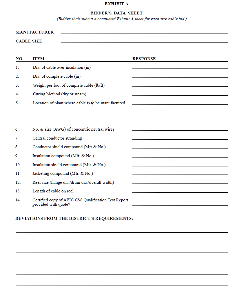
13. Bid Quote Requirements
13.1 Bidder’s shall furnish with their bid quote, a completed Exhibit A form for each size cable bid. An Exhibit A form is provided on page 8 of this specification.
13.2 The bid quote shall include the Manufacturer’s most current written certified copy of the AEIC Qualification Test Report for the compounds, materials, design and processes which are to be used in manufacturing the specified cable. (Exception: This document may be provided in advance of the bid quote. See Section 8.4.2 for mailing address.)
14. General Bidding Conditions
The attached General Bidding Conditions are made part of this specification.