634015.1 1Ø Padmounted Transformers
Click here for a PDF of this Material Standard
Revision 12
Aug 17, 2020
1. Scope
This specification covers the requirements for furnishing and delivering single phase, 60-Hz, mineral-oil-immersed, self-cooled, low-profile, pad-mounted, compartmental-type distribution transformer(s) rated 167 kVA or smaller, suitable for use on a 12.47 Grd Y/7.2kV electrical distribution system.
2. Reference Standards
All characteristics, definitions, terminology, voltage designations and tests, except as otherwise specified herein, shall be in accordance with the following industry standards for distribution, power and regulating transformers. When the following standards are superseded by an approved revision, the revision shall apply.
Industry Standards
ANSI/AIM BC2-1995Uniform Symbology Specification - Code 39
ANSI C57.12.00-2010IEEE Standard General Requirements for Liquid-Immersed Distribution, Power, and Regulating Transformers
ANSI C57.12.25-1990 American National Standard for Transformers—Pad-Mounted, Compartmental-Type, Self-Cooled, Single-Phase Distribution Transformers with Separable Insulated High-Voltage Connectors; High Voltage, 34 500 GrdY/19 920 Volts and Below; Low Voltage, 240/120 Volts; 167 kVA and Smaller—Requirements
ANSI C57.12.28-2014 IEEE Standard for Pad-Mounted Equipment — Enclosure Integrity
ANSI C57.12.35-2013IEEE Standard for Bar Coding for Distribution Transformers
ANSI C57.12.37-2006IEEE Standard for the Electronic Reporting of Distribution Transformer Test Data
ANSI C57.12.70-2011IEEE Standard Terminal Markings and Connections for Distribution and Power Transformers
ANSI C57.12.80-2010IEEE Standard Terminology for Power and Distribution Transformers
ANSI C57.12.90-2010IEEE Standard Test Code for Liquid-Immersed Distribution, Power, and Regulating Transformers and IEEE Guide for Short Circuit Testing of Distribution and Power Transformers
IEEE 386-2006 IEEE Standard for Separable Insulated Connector Systems for Power Distribution Systems Above 600 V
DOE Title 10 Part 431.191Distribution Transformers — Energy Conservation Standards and Their Effective Dates
NEMA 260-1996 (R2004)Safety Labels for Pad-Mounted Switchgear and Transformers Sited in Public Areas
NEMA TR 1 (R2000)Transformers, Regulators & Reactors
District Standards
Material Standard 386202.1 2-1/4" Labels for Marking District Owned Equipment
Material Standard 890526.1 Padmount Equipment Danger Label
Material Standard 890534.1 Padmount Equipment Warning Label
Material Standard 1000212.1 Non-PCB Label
3. losses and efficiency
3.1 No-Load Losses
No-load losses (core losses) shall be quoted in watts, referenced at 20°C in accordance with ANSI C57.12.00-2010.
3.2 Load Losses
Load losses (winding losses) shall be quoted in watts, referenced at 85°C in accordance with ANSI C57.12.00-2010.
3.3 Efficiency
Transformers shall meet the efficiency requirements of the U.S. Department of Energy as stated in DOE 10 CFR Part 431, Energy Conservation Program: Energy Conservation Standards for Distribution Transformers; Final Rule, as applicable.
4. Electrical Ratings, Material ID Numbers & DOE Minimum Efficiencies
| kVA Size | High Voltage | Low Voltage | Material ID | DOE Min. Efficiency |
|---|---|---|---|---|
| 15 | 12.47GrdY/7.2 | 240/120 480/240 |
634015 1000186 |
98.82% |
| 25 | 12.47GrdY/7.2 | 240/120 | 634263 | 98.95% |
| 37.5 | 12.47GrdY/7.2 | 240/120 | 634312 | 99.05% |
| 50 | 12.47GrdY/7.2 | 240/120 | 634510 | 99.11% |
| 75 | 12.47GrdY/7.2 | 240/120 | 634718 | 99.19% |
| 100 | 12.47GrdY/7.2 | 240/120 480/240 |
634916 634924 |
99.25% |
| 167 | 12.47GrdY/7.2 | 240/120 | 635112 | 99.33% |
5. Construction
The pad-mounted compartmental-type transformer shall consist of the transformer tank with a high-voltage and low-voltage cable terminating compartment. The transformer tank and compartment shall be assembled as an integral unit, tamper-resistant, weather-resistant, and designed for flush mounting on a flat rigid surface. The padmounted transformer shall meet the construction and security requirements of ANSI C57.12.25-1990 and ANSI C57.12.28-2014.
5.1 Transformer Tank
A minimum of 13 gauge steel shall be used to construct the transformer tank. The frame shall be constructed in such a manner to prevent distortion of the cabinet during installation and use.
The transformer tank cover shall be either bolted or welded. Bolted covers shall be removable only after being unfastened from inside the cable termination compartment.
The transformer tank roof shall be crowned so as to shed water.
5.2 Transformer Door
The transformer shall be equipped with a single lift up door to provide access to the cable terminating compartment. The roof of this door shall be crowned so as to shed water. A barrier shall not be installed between the high and low voltage segments of the cable terminating compartment (refer to Figure 1 of this Specification).
There shall be a minimum 10-inch separation between the exposed end of the low-voltage terminal studs and the inside of the cable terminating compartment door in the closed position.
The high and low voltage compartment door shall have a suitable means for locking with a padlock. Additionally, a captive nut and captive, recessed pentahead bolt shall be provided for security of the compartment door. A blind bolt hole shall be provided. The design of the captive and recessed bolt shall be in accordance with ANSI C57.12.25-1990, Fig. 3. Bolts shall be stainless steel or bronze and their design shall minimize the possibility of misalignment and cross threading.
Hinge pins must be stainless steel or other non-corrosive metal.
5.3 Limiting Overall Dimensions
Footprint transformer dimensions shall not exceed those shown in Figure 1 of this Specification.
5.4 Cable Terminating Compartment
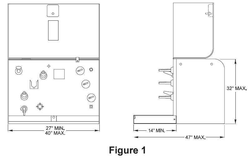
The dimensions of the cable entrance opening in the cable terminating compartment shall be 27-inch minimum width by 14-inch minimum depth (refer to Figure 1 of this Specification).
5.5 Parking Stand
The parking stand shall be mounted in accordance with ANSI 12.25-1990, Figure 2. The maximum center-to-center spacing between the high-voltage bushings and the parking stand shall be 6-inches.
5.6 Grounding Nuts
Two grounding nuts or tapped steel pads (1/2”-13 UNC) shall be provided welded directly to the transformer tank (refer to ANSI C57.12.25-1990, Figure 2 for mounting details). The nuts or pads shall be fitted with removable plastic plugs prior to transformer shipment. Each grounding nut shall be preinstalled with compatible bronze grounding lugs per the following table:
| Manufacturer | Part Number |
|---|---|
| Fargo Mfg. | CG-207 |
| Richards Mfg. | RTG512-M |
| Maclean Power Systems | BVC-207 |
| Eritech Specialty Products | CC-207 |
5.7 Lifting Lugs
Lifting lugs shall be provided in accordance with ANSI C57.12.25-1990, Section 6.1.6.
5.8 Finish
The transformer shall have a corrosion resistant finish that meets or exceeds the coating system requirements of ANSI C57.12.28-2014. The topcoat color of paint shall be semi-gloss Munsell Number 7GY 3.29/1.5, pad-mount green.
Combined thickness of primer and topcoat shall be no less than 3.0 mils. All finish components shall be lead free.
6. Components
6.1 High-Voltage Terminals
Two high-voltage terminals shall be furnished with universal loadbreak bushing wells conforming to IEEE 386, latest revision, designed to accommodate 8.3/14.4kV 200A loadbreak bushings. Bushings shall be mounted in accordance with ANSI C57.12.25-1990, Figure 2. Bushing wells shall be capable of being removed from the outside for maintenance and replacement.
Each transformer shall be supplied with factory installed 8.3/14.4kV 200A loadbreak bushing inserts per the following table:
| Manufacturer | Part Number |
|---|---|
| Cooper Power Systems | LBI215 |
| T&B/Elastimold | 1601A3R/1601A4 |
| Hubbell Power Systems | 215BI |
Bushing inserts shall be covered with dust caps prior to shipment to prevent contamination or damage.
One high-voltage bushing well shall be so located to provide adequate clearance for installation and use of an 8.3/14.4kV 200A loadbreak feed-thru bushing insert. Four-position bail tabs shall be provided for attachment of the feed-thru bushing insert mechanical clamp.
6.2 Low-Voltage Terminals
Low-voltage terminals shall be fully insulated and meet the impulse level specified in ANSI C57.12.25-1990, Section 6.2.1. These terminals shall be the external clamp type capable of being removed from the outside for maintenance and replacement.
Low-voltage line and neutral terminals shall be copper studs dimensioned and threaded per ANSI C57.12.25-1990, Figure 4(c) and shall be mounted in accordance with ANSI C57.12.25-1990, Figure 2.
All low-voltage line and neutral studs shall have a bronze lock nut installed on them.
Each terminal shall be preinstalled with a 6-position 350KCMIL set-screw secondary connector per the following table:
| Manufacturer | Part Number |
|---|---|
| Polaris | PSMAL350-6R-SNOH |
| Homac | ABD6350-SLL |
6.3 Primary Taps
Transformer(s) with 240/120 volt low-voltage ratings shall not have taps unless specified on the Special Provision Sheet.
Transformer(s) with 480/240 volt low-voltage ratings shall have two (2) 2.5% taps above and below rated voltage unless otherwise specified on the Special Provision Sheet. Tap changers when furnished shall be externally operable.
6.4 Transformer Oil
The transformer shall be shipped with the proper quantity of mineral insulating oil. Oil shall meet the requirements of ASTM D 3487 for Type II (inhibited) oil. At the time the oil is put into the tank it shall contain less than (1) ppm PCB certifiable by a laboratory test approved by the United States Environmental Protection Agency. The insulating oil, or any of its components, shall not be listed by IARC, NTP, OSHA or ACGIH as carcinogens. The successful bidder shall supply an MSDS sheet for each distinct formulation of insulating oil supplied to the District.
Alternative insulating fluids, including ester-based and silicone-based oils may be supplied with prior District review and approval.
6.5 Fusing
Each transformer shall be provided with a bayonet style fuse holder assembly equipped with a valve to minimize oil spillage when the fuse holder is removed. Fuse holders shall be externally removable with a hot stick. Each fuse holder assembly shall be provided with an oil-catching drain or drip plate. The drip shield shall extend out from the transformer tank approximately four inches. Fuse holder shall be fully compatible with Cooper Bay-O-Net fuses.
Each fuse holder shall be equipped with a Cooper dual sensing oil fuse with internal isolation link. according to the following table:
| kVA Size | Fuse Size (amperes) |
Fuse Curve No. | Load Sensing Fuse Element Cooper Cat. No. |
Isolation Link Cooper Cat. No. |
|---|---|---|---|---|
| 15 | 8 | C5 | 4000358C05 | 3001861A02 |
| 25 | 8 | C5 | 4000358C05 | 3001861A02 |
| 37.5 | 15 | C8 | 4000358C08 | 3001861A03 |
| 50 | 15 | C8 | 4000358C08 | 3001861A03 |
| 75 | 25 | C10 | 4000358C10 | 3001861A05 |
| 100 | 25 | C10 | 4000358C10 | 3001861A05 |
| 167 | 50 | C12 | 4000358C12 | 3001861A06 |
| The time current curve is Cooper R240-91-51. | ||||
7. Noise
Transformer sound levels shall not exceed the values listed below when measured in accordance with ANSI C57.12.90-2010:
| Equivalent Two-winding kVA |
Average Sound Level (decibels) |
|---|---|
| 0-50 | 48 |
| 51-100 | 51 |
| 101-300 | 55 |
8. Identification
8.1 Nameplate
A corrosion-resistant nameplate shall be provided which conforms to ANSI C57.12.00-2010. Additionally, the nameplate shall show gallons of oil and total transformer weight with oil.
The following statement shall appear on the nameplate: “Contains less than 1 ppm PCB at the time of manufacture”.
Nameplates shall be bar coded in accordance with ANSI C57.12.35-2013.
8.2 Safety Labels
Safety labels, if specified in the Special Provisions Sheet, shall meet the following requirements.
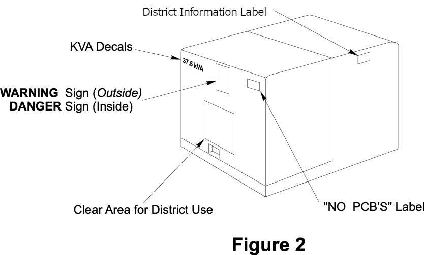
One WARNING sign decal shall be attached to the outside front of the access door and one DANGER sign decal shall be attached to the inside of the access door. WARNING decals shall conform to the latest revision of District Material Standard 890534.1 and DANGER decals shall conform to the latest revision of District Material Standard 890526.1.
The decals shall be centered in the upper one-half of the access door both inside and outside, per Figure 2 of this specification. The bottom edge of the outside warning decal shall be a minimum of eight (8) inches above the bottom edge of the access door.
8.3 kVA Decals
kVA decals, if specified in the Special Provisions Sheet, shall meet the following requirements.
The kVA size of the transformer shall be marked with 2¼” yellow reflective decals in the upper left-hand corner of the front surface of the access door as shown in Figure 2 of this Specification. Marking decals shall conform to the latest revision of District Material Standard 386202.1.
8.4 Non-PCB Decal
 A "NON-PCB" decal, if specified in the Special Provisions Sheet, shall meet the following requirements.
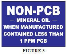
One “NON-PCB” decal shall be attached to each transformer. “NON-PCB” decals shall conform to the latest revision of District Material Standard 1000212.1 (refer to Figure 3 of this specification).
The decals shall be positioned in the upper right corner of the low-voltage compartment door (refer to Figure 2 of this specification). The top edge of the decal shall align with the top edge of the access door.
8.5 Labeling
Each transformer shall be labelled with the following information:
| Line | Data | Length | Example |
|---|---|---|---|
| 1 | District's Material Number* | 11 | "00006303130" *The number 0 must prefix the catalog number to fill 11 characters |
| 2 | District's Material Description | <= 50 | "Transformer, Underground 15 kVA Padmount (L) 240/120" |
| 3 | Date | 8 | "05/22/03" |
| 4 | "PO/REL" space PO Number (8 Characters) space Release Number (5 Characters) | 12 | "PO/REL 00001111 00001" |
| 5 | Transformer Serial Number | 12 | "000125875632" |
The decal shall be durable and weather resistant. The decal shall be placed on the transformer tank cover.
9. Test Reports
The bidder shall furnish certified copies of the short-circuit tests they have performed on each transformer design.
Short-circuit tests shall be in accordance with ANSI/IEEE C57.12.00-2010 and C57.12.90-2010.
The District may reject any bid, when in its judgment, the bidder has not taken sufficient steps to meet the mechanical short-circuit requirements as detailed in the ANSI/IEEE standards.
10. Guarantee
The failure of any transformer due to defective design, material and/or workmanship within 12 months after being energized or 18 months after delivery, whichever comes first, shall be repaired or replaced without cost to the District. Any defect in design, material and/or construction discovered within this period shall be corrected on all transformers furnished on this order at the manufacturer’s expense, either by repair or by replacement.
11. Inspection and Testing
After delivery, all of the delivered lot will be inspected for defects and conformance to this Specification and tested for proper internal connections. The manufacturer (or his representative) will be notified of all defects and mutual arrangements shall be made for correcting the defects at no expense to the District. All subsequent testing required due to the defects will be at the manufacturer’s expense.
12. Packaging
Transformers shall be shipped secured to individual nonreturnable wooden pallets suitable for handling with a forklift.
Transformers shall be shipped in an enclosed van. Transformers shipped on flatbed trucks, even if tarped or otherwise protected shall be refused and returned to vendor.
13. Bidder's Data
For each transformer line item, all bidders shall supply:
- One certified copy of all design tests as called for in ANSI C57.12.00-2010, Table 18.
- All data and information as requested on the attached bidder's data file.
A description of any proposed changes, additions or exceptions to the Specification shall be submitted along with reasons for the departure.
14. Data to be Furnished by the Successful Bidder
14.1 CAD Drawings
A CAD drawing outline dimensions of each transformer line item with accessories. Acceptable formats include Microstation, AutoCAD or DXF.
14.2 Certified Transformer Test Data
Certified data for each transformer shall be submitted for each transformer at the time of shipment or other mutually agreed upon interval. Test data shall reported in electronic form, supplied as an ASCII file with variable length records, comma delimited. Fields shall be stripped of leading and trailing blanks. The data set shall include the standard and extended data sets per ANSI C57.12.37-2006 modified as given:
| Field | Field Name | Data Type | Sample Data | Valid Values |
|---|---|---|---|---|
| 1 | User Name | Char(20) | SNOHOMISH COUNTY PUD | SNOHOMISH COUNTY PUD |
| 2 | User Purchase Order Number | Char(8) | 00026350 | PO number including leading zeros. |
| 3 | User Stock Number | Char(10) | 0000630592 | Mat. ID number including leading zeros. |
| 4 | Producer Identification | Char(2) | HI | See ANSI C57.12.35-2007. |
| 5 | Producer Order Number | Char(14) | 4337 | |
| 6 | Producer Catalog Number | Char(15) | 1037-418997-000 | |
| 7 | Producer Serial Number | Char(13) | 1765201303 | |
| 8 | Product Type | Char(2) | PM | See ANSI C57.12.37-2006, 4.2.8. |
| 9 | Number of Phases | Int(1) | 1 | 1,2 or 3 |
| 10 | kVA Rating | Numeric(7,1) | 37.5 | Nominal ONAN kVA to 1 decimal point. |
| 11 | Primary Voltage | Char(47) | 12 470GrdY/7200 | See ANSI C57.12.00-2006. |
| 12 | Secondary Voltage | Char(28) | 240/120 | See ANSI C57.12.00-2006. |
| 13 | Polarity | Char(1) | S | A (Additive), S (Subtractive), Null (3Ø). |
| 14 | Quoted No-Load Loss | Int(5) | 45 | Quoted no-load losses in watts at nominal kVA, Pri. voltage & 20°C. |
| 15 | Quoted Load Loss | Int(6) | 201 | Quoted load losses in watts at nominal kVA, Pri. voltage & 85°C. |
| 16 | Quoted Impedance Voltage (IZ) | Numeric(4,2) | 2.57 | Quoted IZ in percent at nominal kVA, Pri. voltage & 85°C. |
| 17 | Quoted Excited Current (IEX) | Numeric(4,2) | 0.27 | Quoted IEX in percent at nominal kVA, Pri. voltage & 85°C. |
| 18 | Tested No-Load Loss | Int(5) | 44 | Tested no-load losses in watts at nominal kVA, Pri. voltage & 20°C. |
| 19 | Tested Load Loss | Int(6) | 189 | Tested load losses in watts at nominal kVA, Pri. voltage & 85°C. |
| 20 | Tested Impedance Voltage (IZ) | Numeric(4,2) | 2.6 | Tested IZ in percent at nominal kVA, Pri. voltage & 85°C. |
| 21 | Tested Resistance Voltage (IR) | Numeric(4,2) | 1.66 | Tested IR in percent at nominal kVA, Pri. voltage & 85°C. |
| 22 | Tested Exciting Current (IEX) | Numeric(4,2) | 0.30 | Tested IEX in percent at nominal kVA, Pri. voltage & 85°C. |
| 23 | Total Mass | Int(5) | 892 | Total mass, including accessories & oil. |
| 24 | Mass Unit of Measure | Char(2) | lb | lb (pounds), kg (kilograms). |
| 25 | Date of Manufacture | Char(7) | 2005/05 | Alphanumeric in yyyy/mm format. |
| 26 | Test Data Reporting Lot | Char(7) | 2005/05 | yyyy/mm or yyyy/qx where qx is Q1, Q2, Q3 or Q4. |
| 27 | User Release Number | Char(5) | 00107 | Release number including leading zeros. |
| 28 | Producer Plant Location | Char(10) | MSLAUREL | See ANSI C57.12.00-2006, 4.3.2. |
| 29 | Quoted Loss Guarantee Type | Char(2) | GA | See ANSI C57.12.00-2006, 4.3.3. |
| 30 | No-Load Loss Evaluation Factor | Numeric(5,2) | 5.2 | 00.00 to 99.99 |
| 31 | Load Loss Evaluation Factor | Numeric(5,2) | 1.23 | 00.00 to 99.99 |
| 32 | Frequency | Int(2) | 60 | Nominal operating frequency in hertz, 0 to 99. |
| 33 | Cooling Class | Char(9) | ONAN | ONAN, ONAN/ONAF, KNAN/KNAF or LNAN/LNAF. |
| 34 | Average Winding Temperature Rise | Char(5) | 65 | 55, 55/65, 65 or other as specified. |
| 35 | Type of Insulating Fluid | Char(8) | MIN_OIL | MIN_OIL, FR3, EnviroTemp, R TEMP or as specified. |
| 36 | No-Load Loss Reference Temperature | Int(2) | 20 | 0 to 99. |
| 37 | Load Loss Reference Temperature | Int(2) | 85 | 0 to 99. |
| 38 | Total Volume of Oil | Int(4) | 47 | 0 to 9999. |
| 39 | Volume Unit of Measure | Char(2) | GL | GL (gallons) or LT (liters). |
14.3 Equipment Data Sheet
Each shipment of transformers shall include a digital spreadsheet including all transformers in the shipment and their nameplate data. The spreadsheet shall be formatted to the District’s requirements and shall be emailed to the District’s Standards Department prior to delivery of each transformer shipment. The District will provide the required spreadsheet template to the manufacturer.